background image


Draugystės g. 17 
LT-51229 Kaunas 
E-mail: 

info@trikdis.lt


www.trikdis.com


Summary of Contents for SP231

Page 1: ...Draugystės g 17 LT 51229 Kaunas E mail info trikdis lt www trikdis com ...

Page 2: ...via GPRS using TrikdisConfig or IPcom Control software Transmission of reports Two slots for SIM cards Transmission of encrypted reports to the main or back up CMS IP address via GPRS If GPRS connection is lost the reports shall be sent by SMS messages Continuous control of communication channel Sending of reports when the temperature comes outside the allowable set range Event reports shall be tr...

Page 3: ...onment The control panel was mechanically broken and or intentionally damaged The control panel was damaged due to force majeure lightning discharge etc circumstances The manufacturer shall not be liable for the following control panel malfunctions if the control panel was installed or used not according to its operation manual control panel malfunctions if they occurred upon malfunctioning lost G...

Page 4: ... used housings transformers batteries and programming devices shall comply with the safety requirements established in the Standard EN 60950 The device shall be connected to 230 V voltage 50 Hz frequency mains power through the Class II transformer reducing voltage down to 16 18 V or to 16 24 V direct current source To ensure back up supply a battery of 12 V and at least 7 Ah capacity shall be use...

Page 5: ...PTION OF TRIKDISCONFIG PROGRAM 21 6 3 USER ACCESS 22 6 3 1 Control panel configuration 22 6 3 2 Control panel control 23 6 4 SYSTEM USER INITIAL LOGIN CODES 23 6 5 SYSTEM PARAMETERS 24 6 5 1 General system parameters 24 6 5 2 Resetting of initial parameters 24 6 5 3 Setting of control panel clock 25 6 5 4 Regular connectivity checks 25 6 5 5 Keyboard parameters 25 6 6 SYSTEM TROUBLES 26 6 6 1 Tamp...

Page 6: ... 2000 V PGM1 PGM3 Programmable OC open collector type output terminals for switching on off of various devices automatically or by remote control command create minus 30 V 0 5 A BELL PGM4 Programmable OC open collector type output terminal for automatic switching on of the outdoor or indoor sirens create minus 30 V 1 A LED PGM5 Programmable OC open collector type output terminal with 5 1 kΩ resist...

Page 7: ... formed and the control panel shall automatically switch over the system for its feeding from the back up supply 12 V battery When the battery voltage decreases down to 11 5 V the event Low Battery report shall be formed When the battery discharges below 9 5 V the event Battery Missing Dead report shall be formed and the battery shall be disconnected Upon restoration of the AC mains voltage the AC...

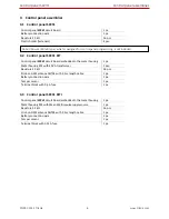
Page 8: ...ormer 1 pcs Resistors 2 2 kΩ 16 pcs Stick on GSM antenna ANT04 with 2 5 m length cable 1 pc Battery connection wire 1 pc Tamper sensor 1 pc Terminal block with 0 5 A fuse 1 pc 3 3 Control panel SP231 KITi Control panel SP231 circuit board embedded in the metal housing 1 pc Metal housing K02 with Mean Well impulse supply source 1 pc Resistors 2 2 kΩ 16 pcs Stick on GSM antenna ANT04 with 2 5 m leng...

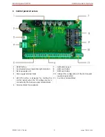
Page 9: ...ght indication 8 SIM1 card holder 3 Back up supply port 9 SIM2 card holder 4 Main supply terminal block 10 USB port for configuration of the control panel operation parameters 5 BAT_ON button is designed for starting the control panel when the DC voltage source is connected to the back up supply terminal block 11 1 wire bus terminal block 6 Terminal block for peripherals ...

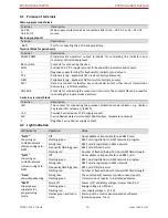
Page 10: ...r e g iButton key reader LED cathode PGM5 5V Positive 1 wire devices 5V DC supply contact 1W 1 wire devices data circuit contact iButton keys temperature sensors C Negative 1 wire devices supply contact 4 2 Light indication LED indicator Operation Value NET2 shows log on to GSM network statuses using card SIM2 Off Not available or impossible to read SIM2 card Flashing green SIM2 card registration ...

Page 11: ...nd places where they should be fastened 5 1 1 Control panel fastening in the mounting housing The control panel circuit board shall be installed into the mounting housing equipped with the reducing transformer with 500 mA fuse and provided place for a back up supply battery Reinforce the control panel into the selected plastic or metal mounting housing using plastic distance holders of the control...

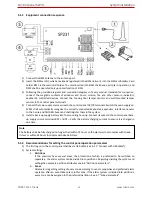
Page 12: ...L GRN buses and shall register them in the system 5 Install a back up supply battery into the mounting housing Connect its wires to the control panel back up supply source terminals BAT BAT Verify the battery charging current to ensure it is charged in due time 5 1 3 Recommendations for setting the control panel operation parameters 1 The first log on to the control panel shall be via USB cable se...

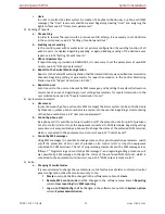
Page 13: ...l a User access In remote mode by phone call and or SMS message the alarm system can be controlled only by those users whose phone numbers are entered into the user list Regarding correct entering of the phone numbers see 6 9 User access parameters b Control by phone call By a phone call it is possible not only to switch on off the protection of all or part of premises but also control start or st...

Page 14: ...tection mode is on the testing mode shall terminate automatically To switch off the mode repeat the procedure as switching it on 5 1 4 2 Testing of report transmission system If GRPS network parameters are correctly set with the Central Monitoring Station addresses upon switching on the power supply to the system the following shall take place a A report E305 System Reset shall be sent b If compat...

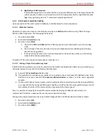
Page 15: ...le to send control panel event reports via internet networks standby 60 mA sending up to 100 mA G10D MCI GSM GPRS communicator able to send control panel event reports via GPRS and or SMS standby 60 mA sending up to 250 mA CZ DALLAS 1 wire iButton key reader up to 25 mA DS18B20 DS18S20 1 wire Temperature sensor Dallas Measuring range from 55 C to 125 C 1 µA 5 3 Connection of sensors The control pa...

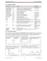
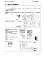
Page 16: ...nput can be dedicated namely for connecting the two wire smoke detectors see 6 7 1 2 Setting of Fire zones Four wire smoke detectors Two wire smoke detectors 5 5 Connection of equipment terminals to PGM outputs PGM1 PGM3 three terminals of open collector BELL PGM4 open collector terminal for connecting the siren LED PGM5 collector terminal with 5K1 resistor Regarding all possible operation modes o...

Page 17: ...erature sensors iButton key readers It is possible to connect iButton key readers and or DS18B20 or DS18S20 temperature sensors to a 1 wire data bus The total length of the bus shall not exceed 30 m with a possibility to connect up to 10 devices Circuit board terminal 5V is designed for supply of 5 V DC to devices connected to 1 wire bus Allowable output current shall not exceed 0 2 A The output s...

Page 18: ...us SK130LED B W Paradox K32 K32LED K636 K10LED keyboards and or input ZN number expanders CZ8 The total length of the bus shall not exceed 300 m with a possibility to connect in parallel up to 16 devices The control panel shall automatically recognise and register the connected devices Regarding device unregistering see Keypads and expanders registration 5 9 Connection of wireless sensors In order...

Page 19: ...rameters After changing the parameters click the software button Write to enter the changes in the control panel memory When configuration is complete shut down the software TrikdisConfig and unplug the USB cable from the control panel USB port 6 1 2 Connect in remote mode Configuration of the control panel settings in remote mode shall be carried out via GPRS communication For both softwares Trik...

Page 20: ...XXXXXX beginning of SMS command and its password 97 5 request about GSM field strength modem IMEI number and control panel software version Example PSW123465 97 5 6 1 2 2 Remote log on through TrikdisConfig 1 Make sure that the control panel is connected to supply source and in operation 2 Start TrikdisConfig software 3 At the field Remote access in the field Unique ID enter the control panel GSM ...

Page 21: ...ons Status bar Name Button meaning Name Value Read F4 Read the control panel parameters IMEI Unique ID IMEI address of the device Write F5 Write the control panel parameters into module Status Action status Open F8 Open the saved file of parameters Device Device type Save F9 Save the file of parameters SN Serial number Help F1 Open the selected help text BL Boot loader version Logout User logout F...

Page 22: ... by clicking Change button at Admin Distributor Code and entering the existing and new codes in the pop up table 6 3 1 2 Installer The lower level of Installer who is able to change Admin allowed parameters Installer access code can be changed by Admin and Installer in the Installer Code field Installer rights can be changed in the Installer permission field Installer rights parameters Name Descri...

Page 23: ...n turn on the preferred arming mode activate or turn off the equipment connected to PGM outputs Control options are provided in the document Control panel SP231 Operation manual 6 4 System user initial login codes Type of code Purpose Factory setting code value Master user To control the system by keyboard 1234 4 digit format 123412 6 digit format Remote user To control the system in remote mode S...

Page 24: ...g current When Grade 2 security is set the control panel must fully charge the battery no longer than within 72 hours or within 24 hours if Grade 3 security is set USER Code Format User control code length 4 digits or 6 digits is to be set In case of 4 digit code and having selected the code format of 6 digits the first two digits are transferred to the end i e Code 1234 will be 123412 Set zn8 as ...

Page 25: ...ecked This setting is on by default in factory settings Connectivity checks can be done in two ways with day based or minute based reference time Settings for connectivity checks can be adjusted in System Options System general Timers Day based reference reports can be sent at the defined time at the specified interval in days Choose Days under the Test period and enter the number of days between ...

Page 26: ...yboard Settings and select Enter code to view system state If security Grade 3 is set the function is enabled automatically 6 6 System troubles For the control panel to display trouble in the keyboard or to send a trouble report after troubleshooting can be set in the program menu System Options System Troubles Also an option to turn on the mode ARM in case of trouble Trouble parameters first part...

Page 27: ...ew trouble When it is checked the necessity for entering the control code to view trouble will be on Enter code to view alarm in MEM When it is checked the necessity for entering the control code to view actuations memory will be on Trouble Shutdown Setting of the allowable number of the same trouble event where in case of excess of such number the trouble reporting will be off The number of such ...

Page 28: ...elected zone line to open such zone settings window Zone parameters Name Description Zn Zone sequence number Input Zone physical address Information displayed module identification number module name ZNx input number P Zone belonging to partition Each zone can be attributed to the preferred partition Bypass When it is checked the option to activate the zone Bypass function during operation will be...

Page 29: ... Line Delay Setting of zone sensitivity The zone events shorter than ones set in the box will not be responded Repeat Insensitive time to recurrent zone events For more details see Shutdown Alarm The maximum allowable number of recurrent zone events For more details on operation see Shutdown 6 7 1 1 Door Chime function At OFF DISARM mode the control panel can for a short while activate PGM output ...

Page 30: ...elay and Exit Delay Interior STAY Operates in the same way as Interior however when security mode STAY or SLEEP is on the control panel will not respond to the zone violations Instant If the zone is violated when the alarm system is on Bell and Flash output signals will be immediately generated and reports sent Instant STAY Operates in the same way as Instant however when security mode STAY or SLE...

Page 31: ...Bell Squawk function is on One short siren output Bell signal will be generated during the alarm system on and two short signals during alarm system off Re ARM Partition arming Re ARM function against accidental alarm system deactivation is enabled When the alarm system is enabled remotely but not violating the entry zone after entry delay time the alarm system will turn on in its previous arming ...

Page 32: ...de registering User Code 4 digit or 6 digit user code for the alarm system control via keyboard is indicated P1 P8 The alarm system partitions controlled by user are indicated 6 9 1 iButton key code registering iButton key numbers are added in iButton code field All added iButton keys will be registered in the order of sequence by clicking Start programming To finish entering the keys click Stop p...

Page 33: ...M card inserted in the module is operating if required by network operator Password User password of GSM operator network where SIM card inserted in the module is operating if required by network operator 6 11 Report transmission to CMS Parameters required to transmit reports to Centralized Monitoring Station CMS via GPRS and SMS communication channels are entered in the program menu Reporting CMS...

Page 34: ...station device able to receive reports via SMS channel Backup 2 communication channel Name Description SMS Phone Phone number of monitoring station device able to receive reports via SMS channel The control panel involves continuous control of communication with monitoring station receiving device Communication testing signals PING are periodically sent to determine performance of communication ch...

Page 35: ...annel is to be indicated If transmission is failed the connection for report transmission via Backup channel will be initiated DNS1 DNS2 IP addresses DNS servers 6 12 Report transmission to user Parameters which set report transmission to users are indicated in program menu Reporting User Reporting The alarm system reports can be sent by SMS messages to 5 mobile phones Events are texted in free fo...

Page 36: ...MS SMS text message sending to indicated telephone is enabled Alarm Restore Alarm system actuation and restoration reporting is enabled Troubles Equipment operation trouble reporting is enabled Open Close Alarm system On Off reporting is enabled Test Misc Communication test reporting is enabled SMS character set SMS character set selection SMS password Password for remote control and programming v...

Page 37: ...nabled Troubles Calling in case of equipment troubles is enabled Open Close Calling in case of alarm system on off is enabled Test Misc Calling in case of communication test is enabled Indicate maximum number of unsuccessful calls in Max number dialing field 6 12 1 Message texts to User Texts which will be visible in SMS messages are indicated in the program menu Reporting SMS text to user SMS tex...

Page 38: ...t is interrupted short circuit Terminal LED PGM5 which is connected to positive terminal of mains supply output via 5K1 resistor It is designed for LED indicator connection PGM outputs are set in program menu PGM Any output can be set operating in one of numerous operation modes see 6 13 1 PGM output operation descriptions PGM output parameters Name Description ID Output sequence number PGM Output...

Page 39: ...ke keyboard buzzer Flash Output for connection of light indicator When the alarm system is on a continuous signalis generated and if the alarm system is disturbed pulse signal Signal is terminated by turning off the alarm system System State Output for connection of light indicator of the alarm system status Within Exit Delay time a pulse signal is generated and when the alarm system activated con...

Page 40: ...ystem status When the alarm system is on a continuous signal is generated Alarm indication Output for connection of light indicator showing alarm status of the alarm system After the alarm system actuation a continuous signal is generated Lost Primary Channel Output where a continuous signal is generated when communication with primary channel was lost Lost Secondary Channel Output where a continu...

Page 41: ...for remote control of partition statuses and PGM remote control mode outputs One call can control one partition selected one PGM output selected selected partition together with PGM output Control by call is available only from phone numbers attributed to the users see 6 9 User access parameters 6 14 1 Partition control By means of call the existing partition mode can be disabled and switched into...

Page 42: ...le address is known click respective field of Type column in such address Slave line To remove module from the list select Not Available in Type field The changes after module adding removing must be written in the control panel This can be done by clicking Write button Transmission modules parameters Name Description Slave Device address number Serial No Module registration number Type Module typ...

Page 43: ...vided in the program menu Keypads Expanders The models connected for the first time will be automatically recognized and included in the list To delete a module check the selected module line and click Remove Keypads and expanders parameters Name Description ID Device sequence number Serial No Control panel registration number Hardware Control panel type Zn Number of control panel inputs PGM Numbe...

Page 44: ...er learn it In all tabs wireless receiver RF MOD will appear after button Update status will be pressed Receiver parameters Name Description RF receiver status When receiver is connected status will change to ONLINE Software version Receiver s software version Hardware version Receiver s hardware version 6 17 1 Detectors In this tab these detectors will be shown PET Immune PIR Detector Magnetic Co...

Page 45: ...vices Rescan all registered devices Add device serial no To register device enter it s serial number and generate event e g tamper Remove devices serial no Using device serial number remove it from device list Detector parmeters Name Description ID Device sequence number Serial No Detector registration number Device type Detector s type RSSI Received signal strength Led Turn on off led Pet For mot...

Page 46: ...p release Learn button 4 In TrikdisConfig window Wireless sensors tab Sirens new sensor will be shown 5 Assign siren to the zone new siren as Siren tamper will be added to the list in the window Zones tab Zones settings Sirens registration Name Description Rescan registered devices Rescan all registered devices Add device serial no To register device enter it s serial number and generate event e g...

Page 47: ...n procedure press the button Start learning 2 Press 3rd and 4rd buttons at the same time orange LED will start blinking 3 When orange LED stops to flash release all two buttons 4 In TrikdisConfig window Wireless sensors tab Pendants new pendant will be shown Pendant registration Name Description Rescan registered devices Rescan all registered devices Add device serial no To register device enter i...

Page 48: ...ntrol panel SP231 Learning 1 To start Learn procedure press the button Start learning Learning window will open Actions with keypad 2 Insert batteries press button C and enter a master code default 0000 3 The tool LED indication turns on 4 Press both SOS buttons at the same time wait until the tool LED indication turns off 5 Press any other button Actions in TrikdisConfig 6 In the TrikdisConfig le...

Page 49: ...smission of temperature variation reports are indicated in the program menu Temperature Sensors When temperature sensors are physically connected and power supply is on the control panel SP231 will automatically register sensor modules Temperature sensor parameters Name Description ID Sensor sequence number Sensor name Sensor name Serial Sensor registration number Numbers can be cleared by enterin...

Page 50: ...formation on events recorded by the control panel is available in the program menu Event Log Events are registered by date and time of the internal clock Memory capacity is at least 2000 last reports Event storage time does not depend on power supply of the control panel and internal battery even if power supply is off the events can be stored for more than 10 years Events are read from the contro...

Page 51: ...rikdisConfig version 2 Connect the control panel SP231 to a computer 3 Open menu branch Firmware of parameter setting software TrikdisConfig 4 Click Open firmware button and check SP231_xxxxxx enc file where xxxxxx upgrade file version In order to save the previously entered data check Preserve settings box 5 To start the control panel software upgrading click Start update After the control panel ...

Page 52: ...ne number Example adding a phone number to the user which code is 1234 CFG123456 01 1234 37061111111 PSWxxxxxx 10 AAA AAA AAA AAA PPPP Set the first IP address and port number AAA AAA AAA AAA IP address PPPP Port number PSWxxxxxx 11 AAA AAA AAA AAA PPPP Set the second IP address and port number AAA AAA AAA AAA IP address PPPP Port number PSWxxxxxx 12 APN LOGIN PSW ENC PING Set SIM1 card access to ...

Page 53: ...e desired partition the number of which P 1 8 S values change numbers 0 into Disarm 1 into ARM 2 into SLEEP 3 into STAY PSWxxxxxx 80 NN S Enable BYPASS mode for the zone the number of which NN NN values zone number 01 32 S values number 1 BYPASS On and 0 BYPASS Off PSWxxxxxx 94 N Enable connection to the Protegus server N values 1 enable 0 disable PSWxxxxxx 96 yyyy mm dd hh mm Set the control pane...

Reviews: