


Control panel SP231
Configuration of control panel operation
©1997-2015 Trikdis
27
www.trikdis.com
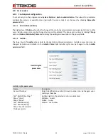
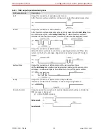
Clock Trouble
Internal-clock time is not set or set inaccurately.
CMS communication Trouble
Connection lost with CMS.
MCI bus Module Trouble
Transmitter is not detected in MCI bus.
Tamper Trouble
Tamper detection.
Zone fault or detector masking
Zone or anti-masking circuit interrupted.
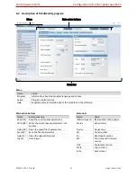
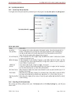
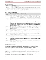
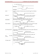
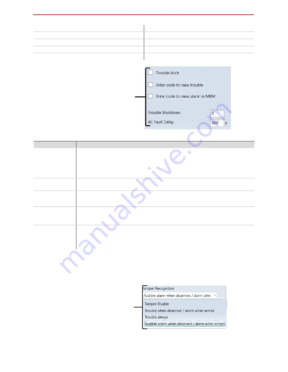
Trouble parameters, second part
Name
Description
Trouble latch
When it is checked, the function of troubles storage in memory will be on. Then, User
wishing to enable the arming first of all must review the troubles occurred and clear
their memory, and afterwards enter its code and enable the arming. If it is not checked,
the trouble indication will operate in real time (trouble occurs - keyboard LED indicator
is lighting).
Enter code to view
trouble
When it is checked, the necessity for entering the control code to view trouble will be
on.
Enter code to view
alarm in MEM
When it is checked, the necessity for entering the control code to view actuations
memory will be on.
Trouble Shutdown
Setting of the allowable number of the same trouble event, where in case of excess of
such number the trouble reporting will be off. The number of such events is counted
until the arming mode is changed (On/Off)
AC Fault Delay
Delay in generating the report on AC network interruption/recovery. Response time to
short-term AC network interruption/recovery is to be set, i.y. report on
interruption/recovery will not be generated if the event time is shorter than set in the
box.
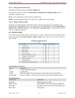
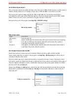
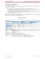
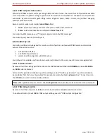
6.6.1
Tamper recognition
How the control panel will operate after tamper recognition can be selected in the program menu System
Options > System Troubles > Tamper Recognition. How to enable the zone tamper tracking, see 6.7 “Zone
parameters”.
Operation after tamper event
Trouble parameters, second part


