background image

Gebrüder TRILETY Ges.m.b.H. 

MCK-M31 1.02 

09/ 2018


* Optional equipment 

Page

 8


1.9 

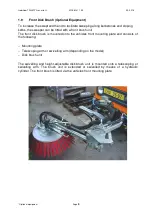
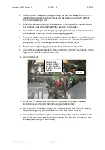
Front Disk Brush


(Optional Equipment) 

To increase the swept width and to facilitate sweeping along kerbstones and sloping 
kerbs, the sweeper can be fitted with a front brush unit. 
The front disk brush is mounted onto the vehicles front mounting plate and consists of 
the following: 
 

  Mounting plate 

  Telescoping arm or swivelling arm (depending on the model) 

  Disk brush unit 

 
The  swivelling  and  height-adjustable  disk  brush  unit  is  mounted  onto  a


telescoping  or 

swivelling  arm.  The  brush  unit  is  extended  or  swivelled  by  means  of  a  hydraulic 
cylinder. The front brush is lifted via the vehicles front mounting plate. 


Summary of Contents for M31

Page 1: ...ebrüder TRILETY Ges m b H MCK M31 1 02 09 2018 Optional equipment Page 1 INSTRUCTION MANUAL STREET CLEANER MCK FOR MULTICAR FUMO M31 Specifications Operating Instructions Maintenance List of Spare Parts ...

Page 2: ...UCTIONS 12 2 1 SAFETY TIPS 12 2 2 PREPARATION OF THE Multicar CHASSIS 14 2 3 MOUNTING AND DEMOUNTING THE SWEEPER 14 2 3 1 Mounting the Sweeper Unit 14 2 3 2 Demounting the Sweeper Unit 16 2 4 Sweeping operation 18 2 4 1 Filling the spray water tank 18 2 4 2 Controls Multicar Vehicle 19 2 4 3 Control panel MCK sweeper 21 2 4 4 Information for operating the vehicle 21 2 4 5 Starting the sweeping ope...

Page 3: ...aning 38 3 4 2 Fan Impeller Bearing 39 3 5 Sweeping and suction unit 40 3 5 1 Basic Settings 40 3 5 1 1 Suction Hood 40 3 5 1 2 Disk Brush 41 3 5 2 Adjustments 43 3 5 2 1 Suction Hood 43 3 5 2 2 Disk Brush 43 3 5 2 3 Front Brush 45 3 6 Hydraulic system 46 3 6 1 Safety Tips 46 3 6 2 General Information 46 3 6 3 Checking the Hydraulic Oil Level 47 3 6 4 Checking the Hydraulic Oil Temperature 47 3 6 ...

Page 4: ...cle length with front brush approx 6 300 mm Vehicle width 1 600 mm Vehicle height approx 2 100 mm Total weight without optional equipment approx 3 180 kg Payload approx 1 620 kg Noise level at engine speed 1 800 rpm 78 5 dB A Mean value Noise level at the driver s position window closed 76 8 dB A Noise level at the driver s position window open 77 4 dB A The sweeper unit should be only used to cle...

Page 5: ...road bays and sloping kerbs Rear mounted hand suction hose to empty gully holes or sucking up leaves Hopper made entirely of aluminium Weight saving approx 300 kg Spotlights for sweeping in the night Rotating flashing beacon on the hopper roof Rear view camera with monitor in the cab 1 3 Construction And Function The entire sweeper unit consists out of the following Base Framework Hopper Fan Unit ...

Page 6: ... in diameter connects the suction hood to the hopper A rubber lined baffle plate is installed above the suction air inlet of the hopper The sucked air then flows via the filter plates fitted on the upper right and left hand sides of the hopper through the air duct into the suction fan and then is dispersed over the exhaust air duct The contents of the hopper are emptied through a large flap that c...

Page 7: ...e swivelled to the side of the vehicle when the hopper is emptied Lifting arm lifts and lowers the sweeping and suction unit Floating arm automatically adjusts so the sweeping and suction units are parallel to the road surface even when the road slopes Suction hood with suction hose Bulky debris pick up flap 2 disk brush units The suction hood with suction hose is mounted in the middle of the floa...

Page 8: ...ont brush unit The front disk brush is mounted onto the vehicles front mounting plate and consists of the following Mounting plate Telescoping arm or swivelling arm depending on the model Disk brush unit The swivelling and height adjustable disk brush unit is mounted onto a telescoping or swivelling arm The brush unit is extended or swivelled by means of a hydraulic cylinder The front brush is lif...

Page 9: ...es on the separate control panel for the sweeper unit 1 11 Electric System All electrical contacts plug and sockets that are used for the connections between the vehicle and the sweeper unit are to be weekly sprayed with a commercial contact spray to prevent corrosion and the possibility of error conditions The sweeper is fitted with a 12 volt electric system The power is supplied via the electric...

Page 10: ...ed Overpressure valve Solenoid valves to actuate the spray nozzles Spray nozzles Disk brushes 2 nozzles each brush Suction hood 5 nozzles Front brush 4 nozzles Water filling hose with C coupling and hydrant key Water hose with spray pistol The water tank is filled using a pressureless none return flow system which conforms to the requirements of the protection of drinking water from contamination ...

Page 11: ...eping and suction units The suction fan generates a vacuum in the hopper this vacuum then sucks the sweeping through the suction hood and the flexible suction hose into the hopper Due to the much larger cross section in the hopper the speed of the sucked air is considerably reduced and the debris then settles in the hopper A rubber lined baffle plate fitted above the suction connection piece in th...

Page 12: ...ce on the suction fan should only be performed after the fan impeller has stopped For safety reasons the ignition key of the vehicle should be removed and kept in a safe place that is inaccessible for other people Before driving the vehicle ensure that the rear sweeping and suction unit is correctly positioned and locked onto the vehicle also ensure that the brushes are in the raised position and ...

Page 13: ... vehicle chassis Note Additionally the safety tips specified in the following chapters must also be observed under all circumstances Note In addition the safety regulations for operating the vehicle must also be observed under all circumstances see separate manual The information left and right are always related to the direction of travel forward drive ...

Page 14: ...onto a Multicar chassis that has been pre fitted with the appropriate equipment with a few easy steps To ensure easy connection the supply lines and cables hydraulics electrics water are fitted with quick release couplings Caution Special care should be taken when changing the attachment high risk of accidents by incorrect performance 2 3 1 Mounting the Sweeper Unit 1 Remove the tipping platform f...

Page 15: ...joints are correctly inserted in the receptacles Insert the safety pins underneath the ball joints 8 Remove the support legs from the holding tubes and store them 9 Connect the hydraulic hoses for the suction fan on to the connectors on the right hand side behind the drivers cab 10 Connect Leakoil 11 At the rear of the vehicle connect the hydraulic hose quick release connections according to the n...

Page 16: ...ace Before demounting the sweeper unit completely empty the hopper and the water tanks and thoroughly clean the brushes and the hopper 1 Drive the Multicar vehicle with mounted sweeper to a parking area with firm level ground 2 Before driving the vehicle ensure that the rear sweeping and suction unit is correctly positioned and locked onto the vehicle also ensure that the brushes are in the raised...

Page 17: ...he vehicle tipping cylinder to the vehicle hydraulic system 15 Mount the tipping platform to the vehicle using the vehicle manufacturer instructions Model with Front brush 16 Disconnect the hydraulic couplings and water pipe at the front of the vehicle 17 Loosen and swing out the retaining screws on the left and right hand side of the mating plate 18 Lower the front mounting plate until the mating...

Page 18: ...eeping unit 4 Tip the hopper up a little so that the items in the storage basket can be reached Caution for sweeping and suction unit 5 Switch the vehicle off 6 Remove the blank cover from the hydrant open the hydrant for a short time to wash any accumulated dirt away so that this dirt can not enter the water tank 7 Remove the blank cover from the water inlet port on the front right hand side 8 Pl...

Page 19: ...see original multicar manual Adjust hydraulic flow with regulator in cabin or on hydraulic block right side behind drivers cab Hydraulic oil quantities Suction fan appr 50 55 l min Actuators and actuating functions 13 15 l min For settings see operating instructions Multicar chassis 4 Brush drive ON OFF 3 Suction Fan ON OFF 2 Hydraulic system ON OFF 1 Hydraulik drive on Adjust vehicle motorspeed ...

Page 20: ... 02 09 2018 Optional equipment Page 20 Speedregulator brushes adjust 12 15 l min Speedregulator suction fan adjust 55 l min Frontbrush raise lower Frontbrush left right and slope Adjust on hydraulic valve block on left side beside battery ...

Page 21: ...e safety tips specified under section 2 1 During the sweeping operation the front lifting device of the chassis must be adjusted to the working height using the fastening chain or locked mechanically While sweeping the driving speed is dependent on the type and quantity of debris and generally lies between approx 2 5 km h In standard operation an engine speed of 2000 2200 rpm is sufficient If the ...

Page 22: ...n using the Multicar vehicle switches see Multicar manual 6 Adjust the vehicle engine speed to the specified speed using the manual throttle 7 Switch the brush drive units on using the appropriate switch see Multicar manual 8 Switch the suction fan on using the appropriate switch see Multicar manual 9 Turn on the floating position of the front brush by briefly pressing the joystick 33 forward Sele...

Page 23: ...be closed The suction efficiency is greatly diminished if the bulky debris pick up flap open When sweeping at dawn dusk or at night the spotlights for lighting the sweeping area can be turned on switch on the vehicle instrument panel Do not sweep up very large debris such as boards large branches wires etc such debris can be manually thrown into the hopper through the side observation flaps Under ...

Page 24: ...ince a high brush load pressure greatly increases brush wear and causes unnecessary stress on the hydraulic unit The swivelling width of the rear brushes is regulated by adjusting the stop screws behind the swivelling bracket 2 4 7 Used Water Drainage When the hopper is full and the vehicle is to be driven a longer distance to the dumping site the weight of the vehicle can be reduced by draining a...

Page 25: ...priate switch 7 Lift the rear sweeping unit by pressing and holding switch G until the rear sweeping unit is completely lifted The brush drive and suction fan must be switched off 8 Lift the front brush by moving the joystick contrary to the driving direction 9 Shift the engine into idle speed see manual for the chassis 10 Switch the hydraulics system off using the appropriate switch see Multicar ...

Page 26: ...ear sweeping unit to the side hook the steel retaining cable on the connector that is on the left hand underside of the frame and securing connector of the swivelling frame 8 Switch the power take off drive and the hydraulic system on using the appropriate switches see Multicar manual 9 Fully open the discharge flap lock by pressing and holding switch A on the sweeper control panel hold for at lea...

Page 27: ...n using the switch C on the control panel in the cab 14 Clean the hopper using the water jet from the spray pistol Above all thoroughly clean the filter plates on the upper left and right hand sides of the hopper as well as the rubber seal sealing surfaces and filter screen of the discharge flap Note The filter plates can be removed to facilitate cleaning After cleaning replace and secure the filt...

Page 28: ...e injury if hand between discharge flap and hopper 20 When the discharge flap is fully closed and seals the hopper actuate the discharge flap lock by pressing and holding switch A on the sweeper control panel hold for at least 5 seconds 21 Switch the hydraulic system and the power take off drive off using the appropriate switches see Multicar manual 22 Unhook the steel retaining cable from the con...

Page 29: ...plate between the suction hose and the connection piece and re lock the suction hose on to the connection piece 4 Open the lock of the hand suction hose connection piece and remove the shut off plate 5 Close the lock of the hand suction hose connection piece 6 Disconnect quick release connection for the suction hood water hose from the water supply on the rear right hand side of the sweeper unit a...

Page 30: ...trical cables and does not damage street lamps or other objects within the movement range of the boom Attention Always use ear protectors when working with the hand suction hose 15 When the suction operation has been performed switch the water to the wander hose spray nozzle and the water pump off using switch C 16 Switch the suction fan off using switch 17 Decrease the vehicle engine speed 18 Swi...

Page 31: ...he connection piece and re lock the suction hose on to the connection piece 25 Turn off the rotating flashing beacon If the hand suction hose system is not be used for a longer period of time it should be dismounted and stored in a dark dry place This procedure will extend the life of the hose 1 Loosen the screws that lock the hose fixing strap on the connection piece and disconnect the hose from ...

Page 32: ... system Do not start the high pressure pump without water The following procedure should be performed to use the optional high pressure water unit Note Water tank have to be full and the water filter have to be cleaned before you start to work Open the air bled ball cock valve and leave it open until no air comes out and then close the ball cock valve Only required if the water system is completel...

Page 33: ...d pull the hose out until the required length has been reached the hose is automatically locked in this position Start the washing procedure by pulling the handle grip of the spray pistol After the washing procedure has been completed gently pull on the hose and then let it automatically roll back onto the hose reel Switch high pressure water pump off using the appropriate switch Decrease the engi...

Page 34: ...by pulling the handle of the spray gun During the spraying procedure control the pressure displayed on the pressure gauge manometer max 130bar Adjust the pressure by turning the regulator max 130bar Turn the regulator anticlockwise lower pressure Turn the regulator clockwise higher pressure The maximum pressure of 130 bar must not be exceeded otherwise the pump can be damaged Please control the oi...

Page 35: ...hould only be replaced after the electrical system has been repaired or inspected 3 2 HOPPER 3 2 1 Baffle Plate The baffle plate is fitted above the suction air inlet connection piece in the hopper and must be cleaned after each dumping and also checked to ensure that the rubber lining is intact Note If the rubber lining is damaged or missing the baffle plate can be destroyed within a short time A...

Page 36: ... wastewater ball valve with switch J on main control board Clean filterscreen filter and tube to suction hood 3 2 4 Air Ducts The air ducts in the rear roof of the hopper leading from the filter screens to the suction fan connection must be weekly cleaned from any deposits 3 2 5 Safety Bar Check that the safety bar is functioning correctly each time when the hopper is tipped Hold the filter grid f...

Page 37: ...ter pump running until water no longer exits through the nozzles 5 Switch the water pump off and close all solenoid valves 6 Replace the filter case on the water filter 7 Fill commercially available frost protection into the water system via the filling connection on the water filter Switch on the water pump and open all solenoid valves to distribute the frost protection in the system 3 3 2 Water ...

Page 38: ...nlet into the filter 3 4 SUCTION FAN Caution Maintenance and repairs on the suction fan should be only performed when the fan impeller has been turned off and is stationary Before carrying out maintenance or repairs on the suction fan remove the vehicle s ignition key and keep it in a safe place inaccessible for other people 3 4 1 Cleaning The suction fan and the suction duct of the suction fan mu...

Page 39: ...d check the fan impeller for signs of wear and deposits Note Hard packed layers of dirt on a soiled impeller as well as worn parts of the impeller may become loose due to the generated centrifugal force while operating the sweeper and this can cause the suction fan to be out of balance and this can damage the motor bearings of the hydraulic drive 6 After cleaning and the visual inspection run the ...

Page 40: ...to the specified values While performing these checks the hopper must be completely lowered and empty 3 5 1 Basic Settings 3 5 1 1 Suction Hood Side sealing strips The side sealing strips should be positioned approx 15 mm above the sweeping surface Front bulky debris pick up flap The lower edge of the closed bulky debris pick up flap should be positioned approx 12 15 mm above the sweeping surface ...

Page 41: ... under the brush supporting arm The maximum brush load pressure is given by the dead weight of the brush and brush suspension system The brush load pressure should only be increased if it is absolutely necessary since a high download pressure greatly increases brush wear and causes unnecessary stress on the hydraulic unit Overlap with the suction hood The sweeping pattern from the swung outwards d...

Page 42: ...Gebrüder TRILETY Ges m b H MCK M31 1 02 09 2018 Optional equipment Page 42 Picture shows pattern for right hand brush pattern for left hand brush is mirrored Mind 100mm Driving direction Curb Edge ...

Page 43: ...ted as there is a high risk of injury if the unit is accidentally raised 3 5 2 1 Suction Hood Height and parallelism of the rubber lateral and rear sealing strips should be adjusted when in the lowered position Loosen the rubber strip clamping nuts Insert an suitable spacer between the floor and the rubber sealing strips Adjust the height and parallelism of the rubber strip to the given values in ...

Page 44: ...tions until the adjustments conform with the values specified in section 3 5 1 2 Ensure that the safety tip above is always observed Swivelling width The stop position for the swivelling width is set using the outer stop screw at the rear brush bearing bracket Loosen the locking nut then adjust the length of the screw until the correct position is obtained section 3 5 1 2 the tighten the locking n...

Page 45: ...n the correct position is obtained tighten both nuts Longitudinal tilt The longitudinal tilt forward tilt of the front brush is adjusted using a turnbuckle Adjust the position of the turnbuckle higher or lower until the correct position is obtained only for extendable front brush Perform a test sweeping to check the adjustment repeat the above instructions until the adjustments conform with the va...

Page 46: ...raulic system has been damaged and oil leaks out during the sweeping procedure immediately stop the sweeping procedure and inform the responsible authority e g fire brigade 3 6 2 General Information Cleanliness is of the utmost importance while performing maintenance or repairs on the hydraulic system since a contaminated system inevitably results in service failures and damage to the hydraulic co...

Page 47: ... thermometer integrated into the gauge glass of the oil level indicator The temperature of the hydraulic oil should not significantly exceed 60oC during normal operation Only for short periods temperatures up to 90oC are permissible Long term temperatures above 70 80oC result in premature ageing of the hydraulic oil and may shorten the working life of the hoses and seals A gradual increase in temp...

Page 48: ...possibly leaking out through the ventilation filter Loud noises in the hydraulic system Turn on the vehicle engine and keep the engine running in idle speed turn on the suction fan drive Keep the drive motor of the suction fan running in idle speed After 10 to15 min the bleeding of the hydraulic system is completed Caution If the oil foam in the hydraulic tank increases during the bleeding process...

Page 49: ...Fan is soiled Insufficient fan speed Hydraulic drive is defective Lower sealing strips of the suction hood are not adjusted correctly Tighten the connection piece Clean the suction hose Replace the suction hose Clean the filter plates Replace damaged sealing Clean the fan Increase the motor speed Check the hydraulic system Adjust the suction hood and the rubber sealing Poor sweeping efficiency Wor...

Page 50: ...ehicle manufacturer Excessive amount of dust while sweeping Water solenoid valve is not open Spray nozzles are clogged Water filter is soiled Water tank is empty Water pump is defective Solenoid valve does not respond Electric drive of the water pump is defective Open the correct solenoid valve Clean the nozzles Clean the water filter Fill the water tank Check the water pump Check the electric sys...

Page 51: ... parts customer service Adjustment by customer service Check or replace Hydraulic system makes excessive noise Hydraulic oil level is too low Water or air in the hydraulic oil Suction line is leaking Hydraulic filter is dirty Hydraulic pipes vibrate Refill the tank Replace the hydraulic oil Tighten the screwed joints or replace the line Replace the filter element Replace the fixing tape Hydraulic ...

Page 52: ...ure pump oil level Condition of the brushes Condition of the suction hood sealing Condition of the baffle plate Check the hydraulic system for leaks High pressure water pump oil level After completion of sweeping tasks clean the machine Clean the water filter Weekly or every 35 Working Hours Clean the fan casing Clean the air ducts in the hopper Monthly or every 150 Working Hours Condition and adj...

Page 53: ...Gebrüder TRILETY Ges m b H MCK M31 1 02 09 2018 Optional equipment Page 53 Links und rechts Pendellager Kehraggregat Schwenklager Kehraggregat ...

Page 54: ...Gebrüder TRILETY Ges m b H MCK M31 1 02 09 2018 Optional equipment Page 54 Frontbesen ...

Page 55: ...every 1 200 Working Hours Change the hydraulic oil and oil filter Observe the instructions of the vehicle manufacturer All the electrical connectors for the hydraulic and water solenoid valves should be unscrewed and removed twice yearly and then sprayed with a commercial contact spray ...

Page 56: ...draulic electrical and water components are listed on the corresponding circuit diagram When ordering spare parts to ensure that the correct spare parts are delivered please always specify the machine type construction year and serial number These details are stamped on the TRILETY Machine type plate that is fitted to the machine ...

Reviews: