background image

User's Manual                                                               Rev B / February 2021 / M125 Helium Compressor


97-00020-000    


2          


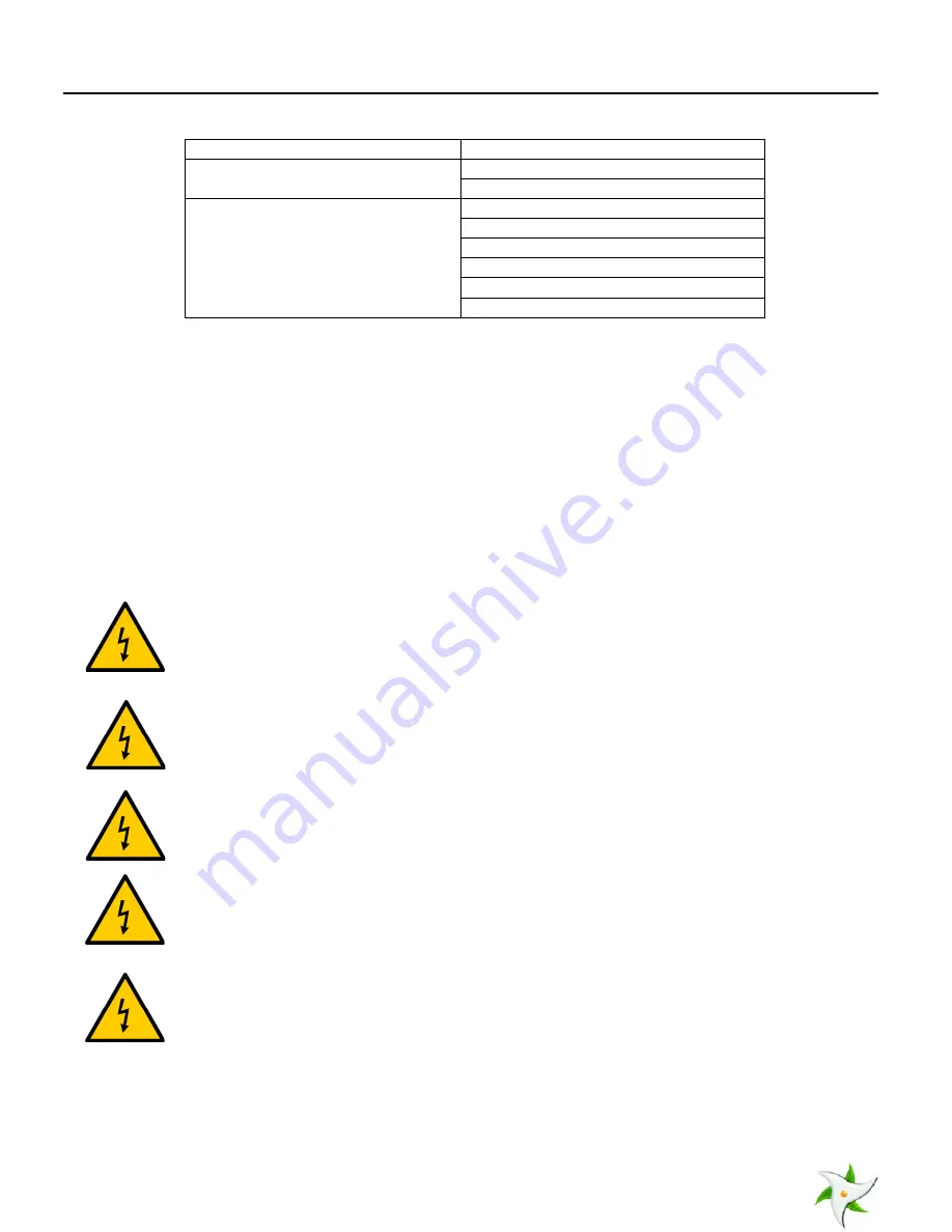
Table 2-1: Compatible Configurations 

Compressor Drive Circuit Configuration 

RC 

Cold Heads 

350CS 

CTI 350 CP 

Cryopumps 

Cryo-Plex 8 

Cryo-Plex 8LP 

CT-8 

CT-8F 

OB-8 

OB-8F 

3


Safety Warnings 

3.1


Standards for the Use of Warnings and Cautions 

Warnings are noted when there is a possibility of injury or death to persons operating the equipment or performing specific 

tasks or procedures noted in this manual. Cautions are noted when there is a possibility of damage to equipment if the 

caution is ignored. 

3.2


Warnings Applicable to All Aspects of M125 Operation 

3.2.1


High Voltage and Electrical Shock Warnings 


 Potentially fatal voltages are present in the compressor unit. Before beginning any work on the 

compressor unit, the compressor needs to be switched off then isolated from the power supply. 


  Connect or disconnect the flex lines joining the compressor and its load (cryopump, cold head, etc.) 

only after the compressor and its load are switched off and separated from the power source.  

Otherwise, electrical shock hazards may exist, potentially causing damage to the compressor unit, its 

load, or the operator.  


  Always provide proper grounding to the compressor unit and its load.  All electrical power connection 

and disconnection of the unit should be done by a qualified electrician. 


  High voltage is present within the compressor unit and can cause severe injury from electrical shock.  

Permit only qualified electrical technicians to open the compressor enclosure to perform electrical 

troubleshooting. 


  Disconnect the compressor from its power source before carrying out any troubleshooting or 

maintenance activities. 


Summary of Contents for 91-00003-0LW

Page 1: ...97 00020 000 Trillium US Inc Model 125 Cryogenic Helium Compressor User s Manual Rev B February 2021...

Page 2: ...or infringements of patents or other rights of third parties This document is the property of Trillium US Inc and by furnishing this information Trillium US Inc grants no license expressed or implied...

Page 3: ...ngs 3 3 2 4 Heat Related Warnings 3 3 3 Operator Instructions 3 4 Introduction 4 4 1 General Information about the Model 125 Compressor 4 4 1 1 Model 125 Features 4 4 1 2 Overview of Model 125 Compres...

Page 4: ...9 8 6 Returning Equipment 19 List of Figures Figure 1 Flow Diagram for Water Cooled Model 125 compressor 6 Figure 2 Flow Diagram for Air Cooled Model 125 compressor 7 Figure 3 Model 125 Dimensions 9 F...

Page 5: ...evise document September 2010 1 1 Conversion to new format Update figures Change adsorber change interval June 2011 1 2 Correct minor typographical errors Add maximum inlet water pressure specificatio...

Page 6: ...nd helium compressors which are refurbished and fully warranted Technical Support Our support engineers will help determine if your cryopump system is operating correctly so that you can get your syst...

Page 7: ...efore beginning any work on the compressor unit the compressor needs to be switched off then isolated from the power supply Connect or disconnect the flex lines joining the compressor and its load cry...

Page 8: ...drawing helium gas from a high pressure gas cylinder Detaching the helium flex lines when the compressor load is at low temperature may cause the pressure to rise in the system beyond the permissible...

Page 9: ...and are charged with ultra high purity 99 999 helium gas The heat exchanger removes the heat generated from the process of compressing helium in the capsule The heat generated by the capsule must be r...

Page 10: ...opens to allow safe operation External relief valve Purpose and Safety Function Opens the helium gas circuit to atmosphere if the helium gas pressure exceeds 350 PSI 24 1 Bar 4 1 4 Operational Flow Th...

Page 11: ...User s Manual Rev B February 2021 M125 Helium Compressor 97 00020 000 6 Figure 1 Flow Diagram for Water Cooled Model 125 compressor...

Page 12: ...User s Manual Rev B February 2021 M125 Helium Compressor 97 00020 000 7 Figure 2 Flow Diagram for Air Cooled Model 125 compressor...

Page 13: ...idth 19 50 inches 495 mm Weight 150 lb 68 kg Helium Pressure Static 190 5 PSIG 13 1 35 Bar Operating 250 10 PSIG 17 24 69 Bar supply Interface Cold head power connector mates with ASC and CTI drive ca...

Page 14: ...W M125 Air cooled Low Voltage Standard Drive Circuit 91 00003 1LA Table 4 5 Optional Accessories and Replacement Parts Accessories Replacement Parts Part Number Adsorber Water cooled model 80034 Adsor...

Page 15: ...to process the insurance information in a timely manner Therefore it is highly recommended that shipping carton be opened and the unit inspected whether or not it will be put into operation right away...

Page 16: ...nit is switched off Never twist the helium flex lines during the installation process Before connecting the helium flex lines follow these steps 1 Identify the helium Return low pressure and Supply hi...

Page 17: ...Detach the coupling of the helium flex line from the helium charge vent valve 8 Close the helium gas regulator on the supply cylinder 9 Seal the helium gas charge vent valve on the compressor unit by...

Page 18: ...g of the frequency switch on the front panel matches the frequency of the power supply where the unit is being installed Failure to do so will result in performance degradation of the system Electrica...

Page 19: ...use 1 AMP Not Shown F1 F2 F3 F4 50081 6 Fuse 3 AMP Not Shown F5 F6 31 00012 018 7 Relay Start K1 50085 8 Meter Elapsed Time ETM1 50089 9 Connector 15 Pin Chassis J1 50087 10 Connector Housing Mate N L...

Page 20: ...e sure any problems associated with water supply or water outlet are resolved Refer to Table 4 3 for proper helium pressure level for the compressor unit If the helium pressure is too low switch off t...

Page 21: ...5 Low power source voltage 6 Mechanical seizure 1 Confirm that sufficient cooling water for water cooled model is flowing to the compressor For air cooled model provide additional cooling to the surr...

Page 22: ...system In severe cases of such oil contamination the load cryopump cold head etc could cease to function completely To remove and replace the compressor adsorber follow the steps described in Sections...

Page 23: ...is depressed 8 Make sure the supply pressure gauge reads 190 5 PSIG 13 1 35 Bar If the pressure is either too high or too low follow the instructions in Section 8 4 1 to fill the helium gas to the pr...

Page 24: ...ge rises to 190 5 PSIG 13 1 35 Bar tightly close the charge valve 4 Insure that the helium charge valve on the compressor is tightly closed Then shut off the helium pressure regulator on the helium bo...

Reviews: