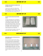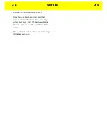
POSITIONING THE BASE LOCATING BRACKETS &
MOUNTING PLATES
Position a bracket & plate assembly 10 cms (4”)
inboard from either end of the Athena Support
Beam. Position the remaining assemblies along
the length of the Athena Support Beam with equal
spacing between each. If one of the bracket
assemblies coincides with a centre frame beam
simply move that bracket to either side of the it.
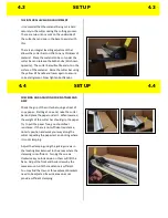
FITTING THE CUTTER ASSEMBLY
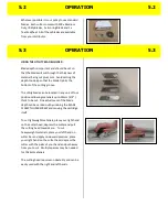
Lift the cutter assembly and place it centrally on
the locating brackets. The larger cutters are
heavy and this will require two people.
Remove the clear stretch wrap and gently
manoeuvre the assembly until it is located
properly on each of the brackets. Slide the
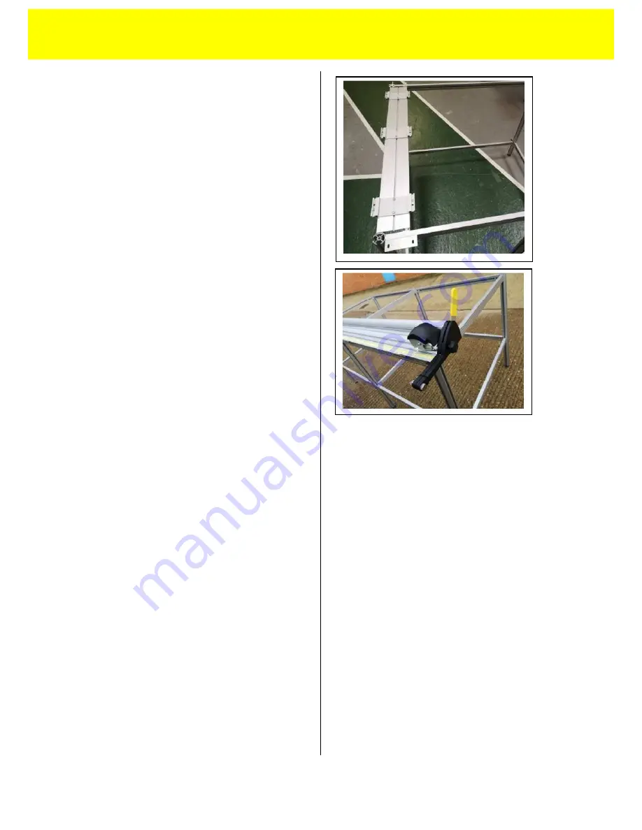
assembly left or right so that the holes in the fixed
arms line up with holes in the support brackets
fitted to the table. Insert the four button head
screws and nuts (included with the table) at this
point but do not tighten.
Loosen by one full turn anti clock-wise, the four
hexagon screws (two at each end) joining the
fixed arms to the cutter base (see 4.2). Now
tighten the four button head screws fully insert
the two wood screws.
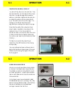
Tighten the grub screws at the back of each
bracket (see 4.1 picture 1) by 8 full turns and then
tighten the front grub screws (see 4.1 picture 2)
up fully (approx 7-8 turns).
The cutter bar is guaranteed to be straight to
within 0.4mm (.016”) along its full length. If you
need to adjust the cutting groove in the base to
match this, follow the instructions in 4.1
7.1 FITTING TO THE ATLAS TABLE
7.1


