ADJUSTING THE CUTTING GROOVE ALIGNMENT
(cont).
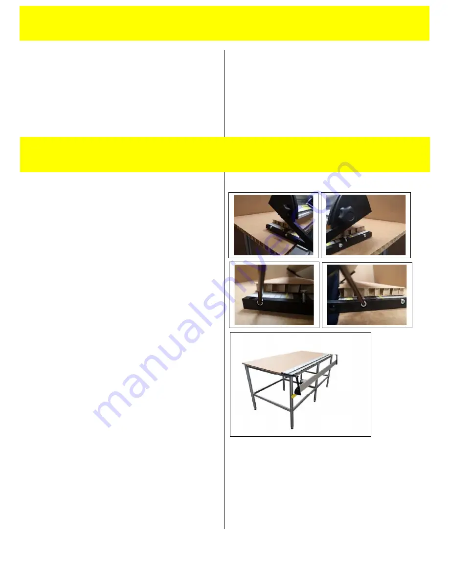
If you find that there is insufficient base alignment
using the adjusting screws it is probable that one
or more of the brackets need to be removed and
realigned on the table top.
THE ROTATING MECHANISM
Insert two of the four wood screws provided in
the front holes of the fixed arm and screw them
into the worktable but do not tighten.
Loosen by one full turn anti clock-wise, the four
hexagon screws (two at each end) joining the
fixed arms to the cutter base. Now fully insert the
two wood screws.
When not in use, the cutter bar can be rotated to
a safe position under the cutting table leaving the
work surface free for performing other
procedures.
NOTE: ASSISTANCE MAY BE REQUIRED, THE
LONGER VERSIONS OF THESE CUTTERS CAN BE
HEAVY
Carefully rotate the bar and place the remaining
two wood screws into the two holes towards the
rear of the fixed arms. Now tighten all four
hexagon screws.
4.2
SET UP
4.2
4.1
SET UP
4.1


