16
ANLEITUNG 04_21
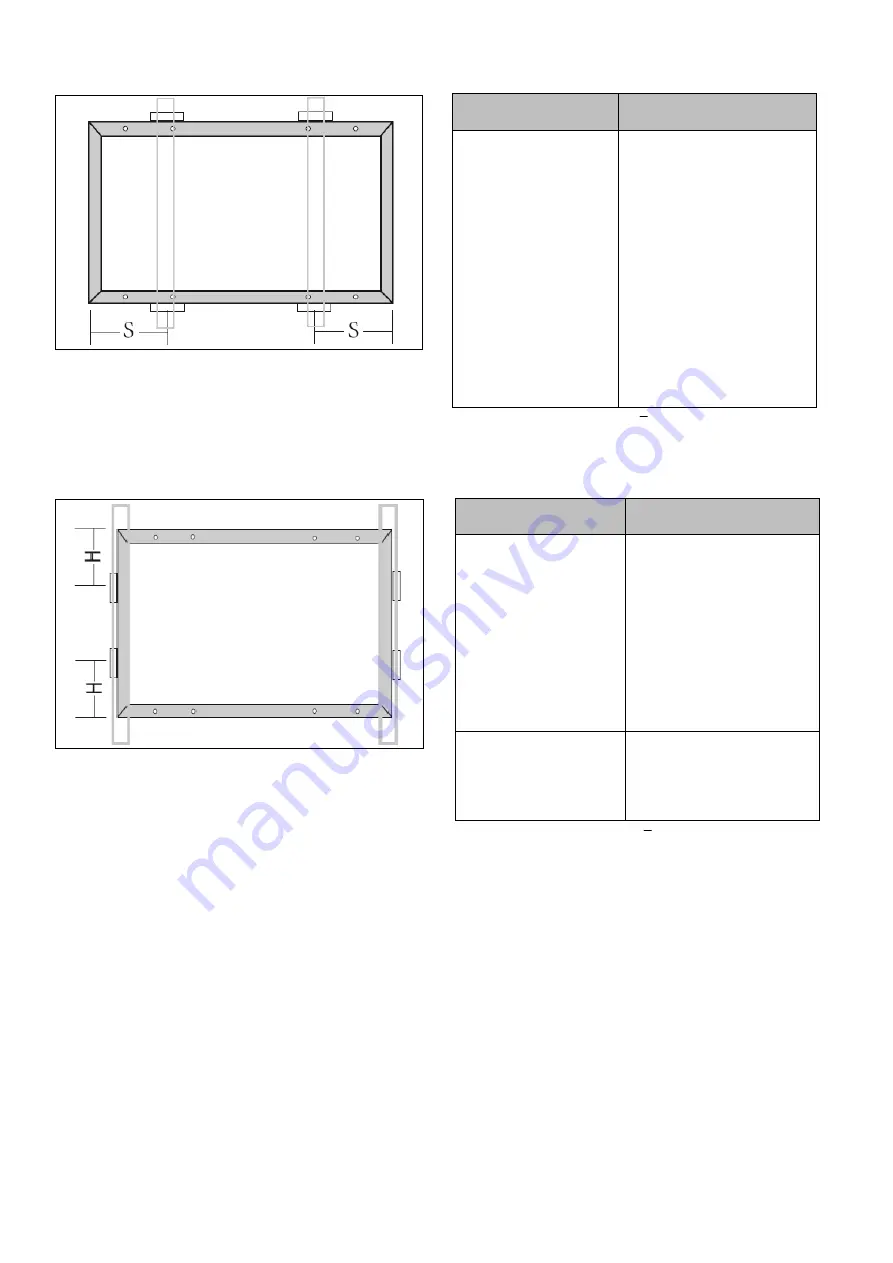
Load capacity - Clamping Long side
Figure 13: Load capacity - Clamping long side
S = ¼L ± 50mm ( clamping position = S ; module length = L )
Module Type
Maximum mechanical load
TMX-MH7-120
TMX-MH7-132
TMX-MH7-144
TMX-MH8-108
TMX-MH8-120
TMX-MH8-132
TMX-MH8-144
TMX-MH9-108
TMX-MH9-120
TMX-MH9-132
Positive: 5400 Pa
Negative: 2400 Pa
Table 8: Approved load capacity Clamping long side
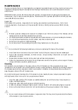
Load capacity - Clamping Short side
Figure 14: Load capacity - Clamping short side
H= ¼W ( clamp position = H ; module width = W )
Module Type
Maximum mechanical load
TMX-MH7-132
TMX-MH7-144
TMX-MH8-132
TMX-MH8-144
TMX-MH9-108
TMX-MH9-120
TMX-MH9-132
Positive: 1200 Pa
Negative: 1200 Pa
TMX-MH7-120
TMX-MH8-108
Positive: 1800 Pa
Negative: 1800 Pa
Table 9: Approved load capacity Clamping short side
Mounting with insertion systems
TRIMAX PV modules are compatible with insertion systems from selected manufacturers. Installation
methods may vary and depend on the mounting structures. Follow the mounting guidelines recommended by
the mounting system supplier. Each module must be held securely along its entire length on two opposite
sides. Mount and tighten the slide-in profiles to the support structure according to the mounting guidelines
using the fasteners provided by the mounting system supplier. The system designer and installer are solely
responsible for load calculations and proper design of the support structure.
The TRIMAX Solar warranty may be void in cases where unsuitable insertion systems or improper installation
methods are found. Please observe the following recommendations when installing slide-in profiles:


