
Page 7 of 14
Part Number 8519184-0000 Rev: B
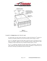
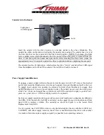
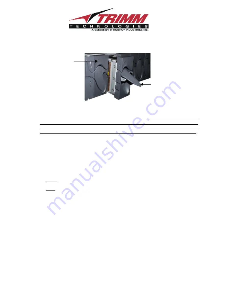
Canister into Enclosure
Insert the canister with the drive in place in a manner similar to the above illustration. The
canister has slides on the sides to help guide the canister into position, The canister has a lever at
the front which cams the canister into the final closed position. (NOTE: To remove, the front
lever is pulled open, which disconnects the drive power. When the power is removed from the
drive it will then park the heads and spin down. After releasing the front lever, pause for
approximately ten (10) seconds to permit the drive to spin down before completing the removal).
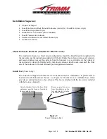
The canister has two (2) light pipes, which carries the drive “Active” (amber/yellow) LED signal
from the midplane to the front of the canister. The red (Drive Fault) is not used.
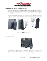
Power Supply Install/Remove
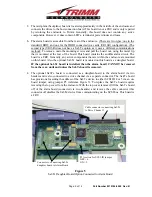
To remove a power supply (reference Figure 4), turn the power switch “off”, remove the attached
power cord, undo the thumbscrews (two for each supply), then grab handle and pull to the rear.
To install, insert supply into opening in enclosure to point where thumbscrews engage, then
tighten thumbscrews to secure power supply in place, then attach power cord, then turn power
switch “on”. (Note, each supply has a green and a red LED to indicate if supply is good or bad –
green on = good; red on = defective supply, needs to be replaced).
Each power supply assembly also houses a fan, power switch and power connection in addition to
the LEDs. If the fan fails the red LED is activated on the supply, along with the alarm and front
panel LED to indicate a failure. The assembly as shown in Figure 4 is the lowest Field
Replacement Unit (FRU).
In a live system, use CAUTION to remove only the failed supply (the one with the red LED on).
CAUTION, with either supply removed, the air flow is misdirected and the drives will overheat
in a matter of minutes, replace supply as quickly as possible in an operating enclosure.
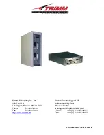
Light pipes
(LED Outputs)
Lever