background image

Page  13 of 14

                  Part Number 8519184-0000  Rev: B

CAUTION:

 Disconnect power before servicing.

ATTENTION:

 Débranchez la puissance avant l'entretien.

The power cord provided may not be suitable for the installation country. It is the
user’s responsibility to insure the power cord satisfies local electrical code.

CAUTION:

 For continued protection against risk of fire, replace only the same

type and ratings of fuse.
Power supplies must be handled with care. If you need to remove a power supply, be
sure not to subject the components to damage (dropping, stacking, etc.).

Warranty:

Trimm Technologies warrants its range of products to be free from defects in
material and workmanship for a period of ONE YEAR from date of manufacture.
The company makes this warranty only to purchasers who acquired the product
direct from the company, its authorized dealers or reps, or others who are
specifically authorized by the company to sell such products. The company’s sole
obligation and the purchaser’s remedy pursuant to this warranty are limited to
repair or replacement, at the company’s option, F.O.B. the company’s plant, of
products which, when used normally and pursuant to the company’s published
instruction, are proven to be defective within the period stated.

The company makes no warranty to purchasers who acquire products for personal,
family or household purposes. No person, firm or corporation is authorized to
assume for the company any liability in connection with the sale or installation of
company’s products except as stated above. THERE ARE NO OTHER
WARRANTIES, EITHER EXPRESS OR IMPLIED, INCLUDING ANY
WARRANTY OF MERCHANTABILITY OR FITNESS FOR ANY PARTICULAR
PURPOSE. The remedies stated herein are expressly set forth, irrespective of the
theory upon which any claim might be based, including breach of contract,
warranty, negligence, or strict liability of tort. Under no circumstances shall the
company be liable for incidental or consequential damages.


Summary of Contents for UR8J2-4 Series

Page 1: ...rt Number 8519184 0000 Rev B Installation Guide for UltraRAID Family UR8J2 4xxx Ultra Rack SCSI 3 Ultra 2 Low Voltage Differential LVD UT8J2 4xxx Ultra Tower SCSI 3 Ultra 2 Low Voltage Differential LV...

Page 2: ...Part Number 8519184 0000 Rev B...

Page 3: ...k 5 Install Feet Tower Enclosure only 5 Install Remove End Caps Rack mount Enclosure only 6 Drives into Canister 6 Canister into Enclosure 7 Power Supply Install Remove 7 Fan Auxiliary Blower Install...

Page 4: ...s are those that conform to SCSI 3 specifications with SCA 2 connections The single ended and host only low voltage differential LVD versions support drives up through SCSI 3 Fast 20 Ultra for transfe...

Page 5: ...lbs 29 55 kg Rack Total with eight canisters and no drives 59 0 lbs 26 82 kg Tower Total with eight canisters and no drives 79 0 lbs 35 91 kg Power Supply 350 watt dual redundant hot pluggable A C 10...

Page 6: ...of 1 channel of 8 drives or 2 channels of 4 drives see Convert 2 x 4 Configuration to a 1 x 8 or vice versa The host connections are identified as SCSI A and SCSI B SCSI A is on the right side rack o...

Page 7: ...4 For a 1 x 8 configuration install the a SCSI jumper cable between the second connectors for the SCSI A and SCSI B connectors The host is connected to SCSI A while SCSI B is either terminated or conn...

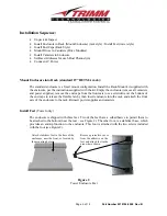
Page 8: ...caps from the front ears use a screwdriver at the bottom of the end caps to release the flexible latch then insert enclosure into the rack and attach the front ears of the enclosure to the rack Reinse...

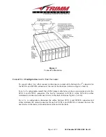
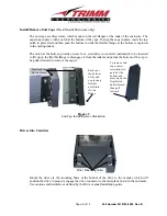
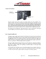
Page 9: ...flexible flange to disengage it from the indent and permit the bottom of the cap to be pulled forward to remove the cap s Figure 3 End Cap Install Remove Illustration Drives into Canisters Mount the d...

Page 10: ...4 turn the power switch off remove the attached power cord undo the thumbscrews two for each supply then grab handle and pull to the rear To install insert supply into opening in enclosure to point w...

Page 11: ...enclosure fans middle LED and temperature bottom LED within the enclosure The temperature LED is red if the enclosure temperature exceeds 45 C Green indicates okay operation while red indicates a prob...

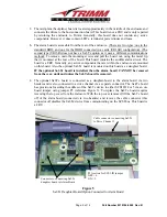
Page 12: ...losure are mounted on this board Also the optional Saf Te board is mounted on this board as a daughter board IF the optional Saf Te board is installed then the alarm board CANNOT be removed from the r...

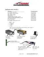
Page 13: ...nt Display Board 5417335 0100 Fan Assembly Auxiliary Blower Fan 5417241 0100 Where color 1 Light Grey 4 Charcoal 5 Black 6 Taupe Power Supply Assembly 350W PFC 5417240 0100 Fan Assembly Auxiliary Blow...

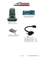
Page 14: ...t Number 5417847 0100 Cable multimode external Part Number 5417823 0100 1 foot Part Number 5417823 0200 3 foot Part Number 5417823 0300 10 foot Part Number 5417823 0400 25 foot Alarm Board Assembly Pa...

Page 15: ...emission construction techniques This equipment generates uses and may emit radio frequency energy If not installed in accordance with the information provided in this manual it may cause interferenc...

Page 16: ...fically authorized by the company to sell such products The company s sole obligation and the purchaser s remedy pursuant to this warranty are limited to repair or replacement at the company s option...

Page 17: ...Trimm Technical Support via US Mailing Address Trimm Technologies Inc 350 Pilot Road Las Vegas Nevada 89119 Phone 702 263 2310 Fax 702 361 6067 Email support trimm com Web Site http www trimm com UK...

Page 18: ...hnologies Inc 350 Pilot Rd Las Vegas Nevada 89119 USA Phone 702 263 2310 Fax 702 260 3443 http www trimm com Trimm Technologies LTD Millennium Way East Phoenix Centre Nottingham England NG8 6AR Phone...

Reviews: