Page 3 of 14
Part Number 8519184-0000 Rev: B
Drive Type(s) Supported:
•
3.5” full-size (1.65” H) and low profile (LP) (1.00” H) (25mm).
•
Hard drive rotational speeds up to 10,000 RPM.
•
Using a Single Connect Attach (SCA-2) type connector (80pin).
•
Low Voltage Differential (LVD) interface, with transfer abilities up to SCSI-3 Ultra
2, at 40 Mhz for data transfer rates up to 80 MB/s (wide interface). also supported are
Single-Ended drives, however, while Ultra 2 permits a mix of LVD and Single-
ended, as soon as one single-ended device is connected into the SCSI bus, ALL of the
transfer rates and cable distances revert to the lowest common denominator, the
single-ended specifications.
•
Drives conforming to the Industry Standard Small Form Factor (SFF) committee
specifications for size and mounting criteria.
Host Connection(s)
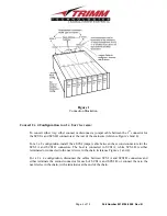
(Reference Figure 1)
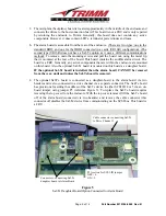
Provides two separate host channels. The host connection is via HD68 type connectors, with each channel
daisy-chaining through four (4) drives in the enclosure, then out to the second connector at the
rear of the enclosure. This second connector must be terminated or daisy-chained to a point that is
terminated.
The enclosure contains two channels of four (4) drives. To set up a configuration of 1 channel of
8 drives or 2 channels of 4 drives, see “Convert 2 x 4 Configuration to a 1 x 8 or vice versa”.
The host connections, are identified as SCSI A and SCSI B. SCSI A is on the right side (rack) or top
(tower), (rear view), with SCSI B on the left side (rack) or bottom (tower), (rear view). Viewing
the enclosure from the front, SCSI A connects to the four (4) drives starting from the left side of
the enclosure. SCSI B connects to the four (4) drives starting with drive bay number five (5),
counting from the left.
The drive addresses are established based on a base address that is set via the Base Address Switch for
each channel. The switches are located at the rear of the unit. SCSI A base address switch sets the
base address for the drive in the bay at the far left (rack) or top (tower), (viewing from the front),
with the next three (3) bays having addresses that are incremented by one for each bay. SCSI B
base address switch sets the base address for the 5
th
drive bay, counting from the left (top), with
each subsequent bay incrementing by one. SCSI B base address sets the base address for these
drives, even if the interface has been jumpered for a one channel by eight drive configuration.
(NOTE: when setting drive addresses, the host address is normally set to 7).
(NOTE: the drive address switches control their respective bank of drives regardless of the
interface configuration, such as a 1 x 8 or 2 x 4 configuration.


