background image

2

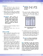
Unpacking

1. While unpacking the valve, check the

packing list against materials received.
Lists describing valve and accessories are
in each shipping container.

2. 

When lifting the valve from shipping
container, position the lifting straps through
the yoke legs to avoid damage to the tubing
and mounted accessories.

WARNING:

When lifting an

actuator with lifting straps
through the yoke legs, be aware
that the center of gravity may
be above the lifting point.
Therefore, support must be
given to prevent the actuator
from rotating.

3. Contact your shipper immediately if there is

shipping damage.

4. 

Should any problem arise, call your
representative.

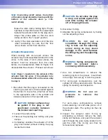
INSTALLATION

1. Before installing the valve, inspect it, and

other associated equipment, for any
damage and any foreign material.

2. Be sure that the body interior is clean, that

pipelines are free of foreign materials, and
that the valve is oriented in such a way that
pipeline flow is in the same direction as the
arrow on the side of the valve.

3. The assembly of the control valve may be

installed in any orientation unless otherwise
limited. However, whenever possible, the
valve should be installed with the actuator
vertical above the body. This is also
important for cryogenic applications to keep
the packing isolated from the flowing
medium, permitting the packing
temperature to remain close to ambient
temperature.

CAUTION:

Do not insulate

extension bonnets that are
provided for hot or cold
services.

4. 

Be sure to allow sufficient overhead
clearance to provide for disassembly of the
plug from the valve body. Refer to 
Table 2 below for overhead clearance
requirements.

Table 2: Overhead Clearance

Requirements

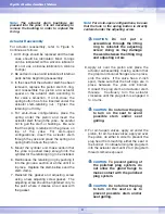
5. If welding the valve into the line, use

accepted piping and welding practices. In
the case that the valve has separable end
flanges, the half rings must be installed on
the body before bolting the valve into the
line in order to insure a tight connection. 

WARNING

:

Failure to install half

rings on the valve body could
result in serious injury.

Note:

Depending on valve body materials

used, post weld heat-treating may be
required.  This may cause damage to internal
elastometric and plastic parts.  Shrunk-fit
pieces and threaded connections may also
loosen.  In general, if post weld heat-treating
is to be performed, all trim parts should be
removed.  Contact your Optimux sales office
for additional information.

Op

G

G

lobe Control Valve

Valve Size

(inches)

1/2, 3/4, 1

1 1/2, 2

3
4
6
8

10
12

Clearance

(inches/mm)

3/76

5/127
6/152
8/203

10/254
13/330
14/356
15/381

Summary of Contents for Optimux OpGL

Page 1: ...shutoff easier to achieve Valve specifications are as follows Table 1 Specifications TABLE OF CONTENTS INTRODUCTION Scope of Manual pg 1 Description pg 1 Specifications pg 1 Safety Information pg 1 U...

Page 2: ...uator vertical above the body This is also important for cryogenic applications to keep the packing isolated from the flowing medium permitting the packing temperature to remain close to ambient tempe...

Page 3: ...the Assembly Disassembly section 1 Inspect end flanges and bonnet for signs of gasket leakage Tighten flange and bonnet bolting if required See Table 4 2 Check the pressure balance sleeve metal bellow...

Page 4: ...ep 2 If valve is air to open apply air under piston to raise the plug off the seat before taking the valve apart 2 Take out the bonnet flange bolting which will allow for removal of the actuator bonne...

Page 5: ...the top guide to enter Different spacer lengths allow a wide variety of packing configurations such as twin seal and vacuum pressure packing WARNING Valves with extended bonnets or metal bellows seals...

Page 6: ...d up against the finger tight body with such force that it will not be possible to wriggle the flange If improper seating occurred the bonnet flange can be wriggled with light hand force If this occur...

Page 7: ...positioned correctly between the bonnet and seat ring 2 Loosen the stem clamp 3 Take out the packing box bolting and yoke clamps 4 Completely unscrew the actuator off of the plug and bonnet without r...

Page 8: ...time until it is in place Replace the stem bellows and the stem clamp 7 Reinstall the gasket and adjusting screw using a new adjusting screw gasket The adjusting screw should be tightened only to the...

Page 9: ...points to the closed position 13 Reconnect the actuator positioner tubing supply and signal lines AIR ACTION REVERSAL Air to Open To switch the air action from air to close to air to open continue as...

Page 10: ...No 88 Yoke Clamp Item No 76 Packing Spacer s Item Nos 94 99 Bonnet Item No 40 Bonnet Flange Item No 70 Anti Extrusion Spacer Item No 93 Adjusting Screw Gasket Item No 248 Spring Button Item No 227 Ac...

Page 11: ...Square Packing w Lubricator Fitting Twin Square Packing w Lantern Ring Braided Wiper Rings 2 Vacuum Seal V packing Vacuum Seal Twin V packing w Lantern Ring Fugitive Emissions Packing PTG PT PTXT Liv...

Page 12: ...12 OpGL Globe Control Valve O S O S Figure 3 Air action Configurations Air to Open Air to Close...

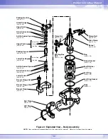
Page 13: ...em No 114 Bonnet Flange Stud Item No 108 Bonnet Flange Item No 70 Figure 4 Exploded View Body Assembly NOTE Item numbers correspond directly to the valve s bill of material Refer to it for specific pa...

Page 14: ...Screw Gasket Item No 248 Cylinder Item No 202 Serial Plate Item No 252 Stem Clamp Item No 249 Stem Clamp Bolt Item No 240 Spring Button Item No 227 Spring Item No 229 Actuator Stem Lock Nut Item No 3...

Page 15: ...service conditions and contact factory 5 Incorrectly adjusted plug 5 Refer to steps 8 10 of Reassembling the Body section for correct plug adjustment 6 Improper flow direction 6 Refer to original spec...

Page 16: ...ly and should not be considered certified or as a guarantee of satisfactory results by reliance thereon Nothing contained herein is to be construed as a warranty or guarantee express or implied regard...

Reviews: