Trina Solar User Manual | Vertex Series Modules
15
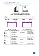
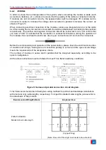
The installation method of clamps is shown in Figure 2.
End clamp installation Middle clamp installation.
Figure 2. PV module installed with clamp fitting method.
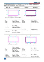
Clamp positions are of crucial importance for the reliability of the installation. The clamp centerlines
must only be positioned within the ranges indicated in table below, depending on the configurations
and loads.
Module type
Maximum loads
Module type
Maximum loads
Use 4 clamps on the long side.
Mounting rails run perpendicular to the long side frame.
Use 4 clamps on the long side.
Mounting rails run parallel to the long side frame.
DE09
DE09.05
DE09.08
A = (250 - 350) mm
Uplift load ≤ 4000 Pa
Downforce load ≤ 6000 Pa
DEG18MC.20(II)
A = (350 - 450) mm
Uplift load ≤ 2400 Pa
Downforce load ≤ 5400 Pa
DE18M(II)
DEG18MC.20(II)
A = (350 - 450) mm
Uplift load ≤ 2400 Pa
Downforce load ≤ 5400 Pa
DEG19C.20
A = (440 - 540) mm
Uplift load ≤ 2400 Pa
Downforce load ≤ 3600 Pa
DE19
DEG19C.20
DE21
DEG21C.20
A = (440 - 540) mm
Uplift load ≤ 2400 Pa
Downforce load ≤ 5400 Pa
DEG20C.20
A = (360 - 430) mm
Uplift load ≤ 2400 Pa
Downforce load ≤ 3600 Pa
DE20
DEG20C.20
A = (360 - 430) mm
Uplift load ≤ 2400 Pa
Downforce load ≤ 5400 Pa
DEG21C.20
A = (440 - 540) mm
Uplift load ≤ 2400 Pa
Downforce load ≤ 3600 Pa


