18
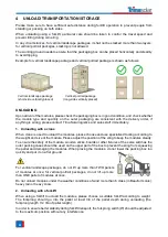
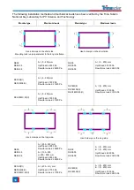
Use 4 clamps on the short side.
Mounting rails run parallel to the long side frame.
/
/
DE09
DE09.05
DE09.08
A = (150 - 250) mm
Uplift load ≤ 2400 Pa
Downforce load ≤ 2400 Pa
/
/
DE18M(II)
DE18M.08(II)
A = (150 - 250) mm
Uplift load ≤ 1000 Pa
Downforce load ≤ 1600 Pa
/
/
6.2.3
SINGLE-AXIS INSTALLATION
The bolts used in this section is to secure the module in each fixing location with an M6 bolt, two flat
washers, a spring washer and a nut, and tighten them to a torque of 16-20 N.m (140-180 lbf.in.).
For Vertex series modules, all parts in contact with the frame should use flat stainless steel washers
of minimum 1.5 mm (0.06 inch) thickness with an outer diameter of 16-20 mm (0.63-0.79 inch),
except for DEG19C.20 using an outer diameter of 16-18 mm (0.63-0.71 inch).
Trina Solar modules can be used with trackers produced by different manufacturers, please check
Appendix A for details.
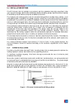
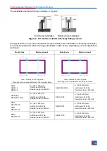
If the tracker is provided with a bumper and hold hoop, they should be tightening together onto the
torque using a hex driver. Please avoid the position of the junction box when installing the bumper.
The module has to be installed on the purlins.
Module type
Maximum load
Module type
Maximum load
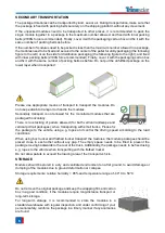
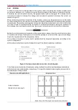
Mounting rails run perpendicular to the long side frame.
Distance between mounting holes is 400 mm.
This installation method is for the tracker with bumper only.
Mounting rails run perpendicular to the long side frame.
Distance between mounting holes is 400 mm.
DEG18MC.20(II)
Uplift
load ≤ 2400 Pa
Downforce load ≤ 2400 Pa
DE18M(II)
DEG19C.20
Uplift load ≤ 2400 Pa
Downforce load ≤ 2400 Pa
* Please note that the mechanical loads for the above two single-axis installation methods are just
regular values, the mechanical loads may different with different trackers, please refer to

