Trina Solar User Manual | Vertex Series Modules
21
6.4.2
WIRING
In order to ensure the normal operation of the system, when connecting the module or loads (such
as inverters, batteries, etc.), observe to ensure that the polarity of the cable is connected correctly.
If modules are not connected correctly, the bypass diode could be damaged. PV modules can be
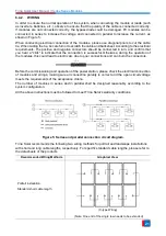
connected in series to increase the voltage and connected in parallel to increase the current, as
shown in Figure 5.
When conducting electrical connection of the modules, please use diagonal pliers to cut the cable
tie. When cutting the tie, be careful not to scratch the cable and backsheet. According to the electrical
requirements. The positive and negative connectors should be connected in turn, and confirm that
you hear a "click" to indicate that the connection is successful. Otherwise, during the operation of
the modules, this could lead to electric arc due to poor connections and can burn the connectors.
Before the commissioning and operation of the power station, please check the electrical connection
of modules and strings, making sure all connection polarity is correct and the open circuit voltage
meets the requirements of the acceptance criteria.
The number of modules in series and in parallel shall be designed reasonably according to the
system configuration.
All the above instructions must be followed to meet Trina Solar's warranty conditions.
Figure 5: Series and parallel connection circuit diagram.
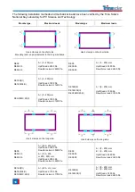
Trina Solar recommends the following two wiring methods for portrait and landscape installations
with short and long cable lengths, respectively. For specific standard cable lengths, please refer to
the datasheets of the products.
Recommended Wiring Methods
Graphical View
Portrait installation:
Standard short cable length
(Note: One end of the single row needs to be extended)
(C-type Wiring)


