background image

Trina Solar User Manual | Vertex Series Modules


23 

PV MODULE MAINTENANCE 

7.1  VISUAL INSPECTION AND REPLACEMENT 

The modules must be inspected and maintained regularly, which is the responsibility of the users. 
The circuit breaker should be disconnected before the inspection. If the modules are damaged, such 
as broken glass, broken cables, and damaged junction boxes, it may cause functional and safety 
failures. If the module is damaged, replace the damaged module with a new module of the same 
type. Do not touch the live part of the cable or connector. 


It  is  recommended  to  perform  a  preventive  inspection  every  six  months,  and  do  not  replace 
components of modules without authorization. If electrical or mechanical performance inspection or 
maintenance is required, it is recommended that qualified professionals should perform the operation 
to avoid electric shock or personal injury. 

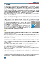
The vegetation should be cut regularly to avoid shading 

and thus affecting the module’s performance. 

Check if the mounting hardware is tightened correctly in place. 

Check whether all string fuses in each non-grounded pole are working properly. 

Please  cover  the  front  surface  of  modules  with  an  opaque  material  during  repairing.  Modules 
exposed to sunlight can generate high voltage, which is extremely dangerous. 

Trina Solar PV modules are equipped with bypass diodes in the junction box to minimize module 
heating and current losses. 


Before cleaning, make sure to wear PPE, such as insulated protective gloves, protective glasses, 
hard hats, safety insulated shoes, etc. 

When using scaffolding, make sure that the scaffolding is in a stable position or with anti-dumping 
measures, and that the installer should wear a safety belt in accordance with local building codes. 

Do not stand on the modules or trackers for cleaning work. 

Do not try to open the junction box to change the diodes even if they fail. 

If the module is damaged (broken glass or scratches on the back sheet), it needs to be replaced.   

It  is  necessary  to  wear  cut-resistant  gloves  and  other  personal  protective  equipment  for  special 
installations. 

Make sure to isolate the impacted array string to prevent the current generation before attempting to 
remove the module. 

Use the relevant disconnect tool provided by the supplier to disconnect the connector of the affected 
module.  

Check the  open  circuit  voltage  of the  array string  and  verify that the  open  circuit  voltage  of other 
strings connected in parallel are within a range of 10V difference. 

Turn the circuit breaker on again after checking. 

Please also pay attention to other safety precautions listed at the beginning of this manual. 

7.2  CONNECTOR AND CABLE INSPECTION 

Inspect all cables to verify that they are firmly connected, avoid direct sunlight, and keep them 
away from water areas.  

It is recommended to check the connectors, torque of bolts, and the general condition of wiring at 
least once a year. Also, check that mounting hardware is fastened in place. Loose connections will 
result in damage to the array. 

Summary of Contents for 210 Vertex Series

Page 1: ......

Page 2: ...DE18M 08 II DE19 DE20 DE21 Bifacial products DEG18MC 20 II DEG19C 20 DEG20C 20 DEG21C 20 Contents of this document are subject to change without notice For the latest document please refer to Trina S...

Page 3: ...INSTALLATION SAFETY 11 6 2 INSTALLATION METHOD 13 6 2 1 SCREW INSTALLATION 13 6 2 2 CLAMP INSTALLATION 14 6 2 3 SINGLE AXIS INSTALLATION 18 6 3 GROUNDING 19 6 4 ELECTRICAL INSTALLATION 20 6 4 1 SAFET...

Page 4: ...manual Warning Otherwise the product may be damaged or the user s personal safety may be endangered Prohibition Otherwise the product may be damaged or the user s personal safety may be endangered 2...

Page 5: ...em Do not artificially concentrate sunlight on the module Do not drop PV modules or allow objects to hit or fall directly on the modules Do not carry modules on your head Do not carry modules with rop...

Page 6: ...is a risk of corrosion if the module is placed in a salt spray i e a marine environment or in an environment containing sulfur e g volcanoes etc In the place 50 500 m away from the sea stainless steel...

Page 7: ...ing to the weight and size of the module Please adjust the position of the sling to keep the modules steady To ensure the safety of the module wooden sticks boards or other fixtures of the same width...

Page 8: ...river it is recommended to drive backwards during the forklift and arrange for special supervision and command to prevent bumping into people or items causing personal injury or damage to the modules...

Page 9: ...dary transport is not allowed for the monofacial modules that are packaged horizontally There is no stacking of pallets allowed for both vertical landscape and vertical portrait packages when transpor...

Page 10: ...cm 5 UNPACKING INTRODUCTION 5 1 UNPACKING SAFETY Before unpacking please check the product type power bins serial number and relevant suggestions on the A4 paper of the packaging box and read the unpa...

Page 11: ...ter of gravity and are prohibited from unpacking on non horizontal or soft grounds to avoid personal injury or even death If unpacking the vertical portrait packages on non horizontal ground anti tilt...

Page 12: ...struction can be seen on the packing box 4 Cut the two packing belts on the short side of the pallet and cut the side carton in the vertical direction 5 Cut off the short side tape lift the cardboard...

Page 13: ...e side cover 4 Take out the modules from one side 1 Remove the wrapping film and packing belts 2 Remove the top cover and sealing tape 3 Remove the carton box 4 Place the stand supporter from the glas...

Page 14: ...s or connectors etc If any of such situation is found please contact Trina Solar customer service in time Before installation please keep modules electrical components clean and dry Connectors can cor...

Page 15: ...nstallation During installation and wiring of PV modules please use opaque material to cover the PV module surface completely Installation work must be carried out by at least two persons Do not stand...

Page 16: ...s and or the professional engineers For detailed information please follow local structural code or contact your professional structural engineer The modules shall be mounted on continuous rails that...

Page 17: ...s modules with a number of clamps from different manufacturers it is recommended to use fixing bolt of at least M8 The clamp should have length of 50 mm 1 97 inch with thickness of 3 mm 0 12 inch The...

Page 18: ...g rails run perpendicular to the long side frame Use 4 clamps on the long side Mounting rails run parallel to the long side frame DE09 DE09 05 DE09 08 A 250 350 mm Uplift load 4000 Pa Downforce load 6...

Page 19: ...M 08 II A 0 200 mm Uplift load 1000 Pa Downforce load 1200 Pa DE18M II DE18M 08 II DEG18MC 20 II A 0 200 mm Uplift load 1000 Pa Downforce load 1300 Pa DEG18MC 20 II A 0 200 mm Uplift load 1000 Pa Down...

Page 20: ...200 mm Uplift load 1800 Pa Downforce load 1800 Pa DE18M II DE18M 08 II A 250 450 mm B 100 250 mm Uplift load 1000 Pa Downforce load 1200 Pa DEG18MC 20 II A 250 450 mm B 100 250 mm Uplift load 1000 Pa...

Page 21: ...roduced by different manufacturers please check Appendix A for details If the tracker is provided with a bumper and hold hoop they should be tightening together onto the torque using a hex driver Plea...

Page 22: ...a Solar s modules The grounding device should be installed in accordance with the operating manual prescribed by the manufacturer Trina Solar recommends using grounding wires with resistances that are...

Page 23: ...es installed in the system In order to ensure this the open circuit voltage of an array needs to be calculated at the lowest expected local ambient temperature which can be determined using the follow...

Page 24: ...Otherwise during the operation of the modules this could lead to electric arc due to poor connections and can burn the connectors Before the commissioning and operation of the power station please che...

Page 25: ...ot responsible for determining the minimum rating of fuse The fuse rated current should be chosen depending on different standards as follows 1 5 1 56 where Fuse rated current A Short circuit current...

Page 26: ...rent losses Before cleaning make sure to wear PPE such as insulated protective gloves protective glasses hard hats safety insulated shoes etc When using scaffolding make sure that the scaffolding is i...

Page 27: ...hen cleaning the back of the bifacial module avoid any sharp objects that may cause damage or penetrate the base material The other cleaning requirements are the same as the front side Cleaning activi...

Page 28: ...ucted with non conductive materials to minimize risk of electric shock and that they are not abrasive to the glass or the aluminum frame If grease is present an environmentally friendly cleaning agent...

Page 29: ...trinasolar com and one of our technical service representatives will contact you within 5 business days A username and password is required to send feedback from the customer service link For module s...

Page 30: ...20 Array Technologies Inc DuraTrack HZ v3 400 mm purlin Uplift load 1600 Pa Downforce load 1600 Pa DEG18MC 20 II DEG19C 20 Array Technologies Inc DuraTrack HZ v3 600 mm purlin Uplift load 2400 Pa Down...

Page 31: ......

Reviews: