background image

PD-013-42 / TMCM-110-42 Manual (V1.24/2011-NOV-25) 

16 


Copyright © 2011, TRINAMIC Motion Control GmbH & Co. KG 


7.2.1.12


Microstep resolution (Z) 

The microstep resolution can be set by the user. It depends on the maximum resolution which differs in the 
three chopper modes (see 7.3). The maximum resolution is divided by the parameter 

Z


Parameter Z 


Microstep resolution 

SPI 

PWM 

Phase (default) 

max resolution 

64 *) 

64 

256 

1/2 max 

32 **) 

32 

128 

1/4 max 

16 

16 

64 

1/8 max 

32 

1/16 max 

16 

1/32 max 

1/64 max 

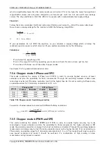
Table 7.10: Adjustment of Microstep Resolution 

*) Simulated microsteps, the actual microsteps of the motor are not improved. 
**) Simulated microsteps, the actual microsteps are improves but do not reach 32 microsteps. 
 

Example: 

AZ 2 

ENTER sets the microstep resolution to a quarter of the maximum resolution. 
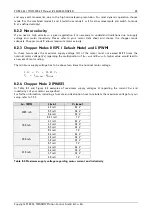
 

7.3


Chopper modes 

7.3.1


Chopper mode 0 (SPI) / default mode 

In  this  mode,  the  motor  coil  current  is  regulated  on  a  chopper-cycle-by  chopper-cycle  bias.  This  is  the 
standard operation mode for most motor drivers. It brings a medium microstep resolution of 16 microsteps 
and typically works well with most motors and a high range of supply voltage and motor current settings. A 
resolution  of  up  to  64  microsteps  can  be  simulated  but  the  motor  precision  is  only  slightly  improved 
compared to 16 microsteps and the same as with 32 microsteps. 
 
The maximum supply voltage (V

S

) of the motor must not exceed 22-25 times the nominal motor voltage (V

N

), 

regarding the multiplication of I

COIL, MAX

 and R

MOTOR

. A higher value would lead to an excess of motor rating. 

The minimum supply voltage has to be above two times the nominal motor voltage. 
 

MOTOR

MAX

COIL

N

N

S

N

R

I

V

V

V

V

,

25

...

22

2


It uses a chopper frequency of about 36kHz. 

7.3.2


Chopper mode 1 (PWM) 

This mode is identical to the SPI mode, but it increases the microstep resolution at low velocities / stand 
still. 
 

MOTOR

MAX

COIL

N

N

S

N

R

I

V

V

V

V

,

25

...

22

2


7.3.3


Chopper mode 2 (PHASE) 

This mode uses a different chopper scheme, which provides a very high microstep resolution and smooth 
motor operation. Care has to be taken concerning the selection of motor and supply voltage:  
The motor is chopped with 20kHz, and the coil sees a 50% duty cycle at full supply voltage when the coil 
current is meant to be zero. This is only true for the average, but the motor still sees an alternating current 
and thus an alternating magnetic field. Now, care has to be taken in order to keep this current to a value 

Summary of Contents for PDx-013-42

Page 1: ...MIC Motion Control GmbH Co KG Hamburg Germany www trinamic com V 1 24 HARDWARE MANUAL TMCM 013 42 TMCM 013 42 LA controller driver up to 1A RMS 30V DC RS485 step direction driver PDx 013 42 controller driver up to 1A RMS 30V DC RS485 step direction driver ...

Page 2: ... 7 2 1 10 Velocity mode V and A 15 7 2 1 11 Store parameters to EEPROM W 15 7 2 1 12 Microstep resolution Z 16 7 3 Chopper modes 16 7 3 1 Chopper mode 0 SPI default mode 16 7 3 2 Chopper mode 1 PWM 16 7 3 3 Chopper mode 2 PHASE 16 7 3 4 Chopper mode 3 Phase and SPI 17 7 3 5 Chopper mode 4 PWM and SPI 17 7 4 Step direction 18 7 4 1 Direction 18 7 4 2 Step 18 7 5 Firmware update 19 7 6 Reset to fact...

Page 3: ...quipment intended to support or sustain life and whose failure to perform when properly used in accordance with instructions provided can be reasonably expected to result in personal injury or death TRINAMIC Motion Control GmbH Co KG 2011 Information given in this data sheet is believed to be accurate and reliable However neither responsibility is assumed for the consequences of its use nor for an...

Page 4: ...iver for general decentralized applications Robotics Remote diagnostics feedback allows for high reliability drives Motor type Coil current from 300mA to 1A RMS 1 5A peak 7V to 30V nominal supply voltage PANdrive Motor data all PANdrive motors optimized for 1A RMS coil current 200 fullsteps per revolution please refer to motor data sheet for detailed motor information Highlights Remote controlled ...

Page 5: ...iption Dimensions mm PD1 013 42 option PANdrive 0 27Nm 53 x 42 x 42 PD2 013 42 option PANdrive 0 35Nm 59 x 42 x 42 PD3 013 42 option PANdrive 0 49Nm 69 x 42 x 42 TMCM 013 option Motion control module for NEMA 17 motors 14 x 42 x 42 TMCM 013 LA option Motion control module for NEMA 17 linear actuators 14 x 42 x 50 Table 3 1 PANdrive and module order codes Option Host interface 485 RS485 Table 3 2 O...

Page 6: ...ve power supply voltage GND 2 GND power VCOM 3 Reference voltage for step direction inputs Positive optocoupler supply Required for negative logic Disable 4 Tie to GND to shut down motor power leave open or at VCOM otherwise Direction 5 Tie to GND to inverse motor direction leave open or at VCOM otherwise Step 6 Step signal optically isolated Cathode of optocoupler Alert 7 Alert output for wiring ...

Page 7: ...e of the TMCM 013 42 is 6 0mm and of the TMCM 013LA 12 5mm TMCM 013 36 5 mm 42 mm 5 5 mm 42 mm 36 5 mm 36 5 mm 21 0 mm 21 0 mm Figure 4 2 Dimensions for TMCM 013 TMCM 013 LA 5 4 mm 44 6 mm 36 4 mm 12 5mm 20 9 mm 20 9 mm 36 4 mm 50 0 mm 41 8 mm Figure 4 3 Dimensions for TMCM 013LA 4 3 Connectors The numbering printed on the 16 pin connector is reversed The red cable is pin 1 Both connectors are cri...

Page 8: ...ly voltage for step direction and disable inputs have negative logic 5 24 27 V VOPTON Signal active voltage at disable step and direction input optocoupler on measured from UCOM to input 3 5 4 5 24 30 V VOPTOFF Signal inactive voltage at disable step and direction input optocoupler off measured from UCOM to input 5 5 0 2 V IOPT Optocoupler current internally regulated 4 8 mA fSTEP Step frequency 3...

Page 9: ...positive supply voltage of the master and the inputs are driven by open collector or push pull outputs VOPTOFF and VOPTON must not exceed VCOM to avoid reverse polavity for the optocouplers OFF VCOM VIN 1 0V ON VCOM VIN 3 5V UCOM 5 24V Disable Dir Step C E A C C E A C C E A C GND µC A Anode C Cathode C Collector E Emitter 5V Figure 5 1 Step direction and disable inputs Examples VOPTOFF VOPTON VSTE...

Page 10: ...user s responsibility to stop the step impulses or set the velocity to zero before enabling the motor again because it starts abrupt otherwise Function Table VOPTON open wire VOPTOFF motor disabled motor enabled 7 2 RS485 interface The RS485 interface can control all functions of the TMCM 013 It is possible to change parameters with this interface which are also valid in the other modes like max v...

Page 11: ...hout moving the motor See command R to read out current value 32 bit 0 Q Read I Os Provides out of the I O the values of the ports GPI REF_A REF_B GPO and ALARM Refer to 7 2 1 7 R Read Current Position Provides the current position of the motor See command P to manipulate this value 32 bit S Changes address byte Capital letter followed by the command S makes this letter the new address byte BS mak...

Page 12: ...ve the 100 setting at any time Not all currents can be continuously driven at all supply voltages and cooling circumstances Please take care of the motor current limitations AC ICOIL PP ICOIL RMS to max ICOIL 100 1 50A 1 06A 100 80 1 20A 0 85A 75 66 1 00A 0 71A 66 50 0 75A 0 53A 50 33 0 50A 0 35A 33 20 0 30A 0 21A 25 0 0A 0 00A 0 Table 7 2 Motor current examples not possible for chopper mode 2 7 2...

Page 13: ...p direction mode the motor will not be stopped when the stallGuard value is reached but the general purpose output will be controlled by the stallGuard value when the actual load value is greater than the stallGuard value the GPO will be switched on and when the actual load value is lower or equal to the stallGuard limit the GPO will be switched off This can be used to signal a stall to the step d...

Page 14: ... The position value of the motor can be changed by the command P When changing this value just the motors positioning counter is changed The motor does no according movement The actual position can be read out by the command R 7 2 1 8 I Os readout Q Command AQ ENTER Bit 7 6 5 4 3 2 1 0 Port 0 0 0 GPI REF_A REF_B GPO ALARM Table 7 8 I Os Readout 7 2 1 9 Baud rate U The parameter U changes the baud ...

Page 15: ...s microsteps n s microsteps v For a 200 step motor at 64 microsteps this results in 85815 s rotations n s rotations v A practical limit for most stepper motor types is ca 20 rotations sec in chopper mode 0 In chopper mode 2 it is 5 rotations sec As a second parameter value 0 or 1 is optional The V command also has a second parameter leaving it out or setting it to 0 will send the carriage return c...

Page 16: ...d a high range of supply voltage and motor current settings A resolution of up to 64 microsteps can be simulated but the motor precision is only slightly improved compared to 16 microsteps and the same as with 32 microsteps The maximum supply voltage VS of the motor must not exceed 22 25 times the nominal motor voltage VN regarding the multiplication of ICOIL MAX and RMOTOR A higher value would le...

Page 17: ...ode combines the modes 2 Phase and 0 SPI in order to provide highest accuracy at lower velocities and also the possibility for faster movements Through the switching between modes some microsteps may be lost Microstep resolution must not be higher than 64 It is set according to Phase mode so possible values for Z microstep resolution are 2 3 or 4 µsteps Phase to SPI SPI to Phase V value Rounds s V...

Page 18: ...connected to VCOM Direction connected to Ground Table 7 12 External signals and motor reactions Motor Speed Step Vcom 0 V Disable Vcom 0 V Velocity Deceleration Acceleration rotating on off const Direction Vcom 0 V rotating direction rotate left rotate right 0 Figure 7 3 Step direction signals and motor reactions 7 4 1 Direction The Direction signal changes the motors rotation from clockwise CW to...

Page 19: ...Table Extern GND open wire VCOM 5 24V Intern HIGH LOW step pulse direction 0 7µs min 2 0µs min 0 7µs min tDIRHOLD tDIRSETUP Figure 7 4 Step and Direction Signal 7 5 Firmware update Start the program TMCM013boot exe for the firmware update available on www trinamic com Figure 7 5 Firmware update tool Choose your RS485 connection Select your Module ID default is A Load the new firmware file e g TMCM...

Page 20: ...odule is not known it makes sense to restore factory default settings switch OFF the module and short circuit pin 1 and pin 3 of the free contacts for a 6 pin connector on the backside of the module Turn on the module and switch it off again for removing the short circuit All settings are now at factory default pin 1 quadratic pin 3 Figure 7 6 Reset to factory default ...

Page 21: ... If the motor heats up very quickly check all settings The motor shall never reach a temperature above 100 C under any circumstances Some stepper motors need contact to metallic parts to allow continuous operation Mind the default settings when you operate in step dir mode the first time You can store your own settings in the module permanently 8 2 1 Motor choice Care has to be taken concerning th...

Page 22: ...e motor must not exceed 22 25 times the nominal motor voltage VN regarding the multiplication of ICOIL MAX and RMOTOR A higher value would lead to an excess of motor rating The minimum supply voltage has to be above two times the nominal motor voltage MOTOR MAX COIL N N S N R I V V V V 25 22 2 8 2 4 Chopper Mode 2 PHASE In Table 8 1 and Figure 8 2 examples of maximum supply voltages VS regarding t...

Page 23: ...motor and power supply 8 3 Power supply requirements The power supply should be designed in a way that it supplies the nominal motor voltage at the desired maximum motor power In no case shall the supply value exceed the upper lower voltage limit To ensure reliable operation of the unit the power supply has to have a sufficient output capacitor and the supply cables should have a low resistance so...

Page 24: ...5 Pin 6 Figure 8 4 Contacts for step direction The maximum step frequency is 350 kHz limited by the optocouplers 8 5 Connections for RS485 interface The RS485 mode allows for configuration of motor parameters as well as remote control of the motor 8 5 1 Interface installation To connect the module to a PC a RS485 interface is required for example TRINAMICs USB 2 485 or any other RS485 adapter like...

Page 25: ...e in Figure 8 6 and confirm with OK Bit rate Data bits Parity Stop bits Flow control none none Figure 8 6 Connection settings for RS485 Type into the terminal window commands like AV 50000 AA 300 or Ac and execute each with ENTER With standard RS485 adapters the typed value may be echoed and lines like AAVV 5500000000 for the typed AV 50000 appear The value sent to the module is the typed one and ...

Page 26: ...HC RS485 command W clarified Figure 8 4 corrected disable 1 22 Addition OK Additional feature of firmware V1 12 stallGuard with step direction added 1 23 Correction OK Address setting procedure corrected 1 24 Correction SD Order codes new new design minor changes Table 9 1 Document revision 9 2 Firmware revision Version Comment Description 1 05 Pls update 1 07 Bug fix Full functionality with some ...

Reviews: