PD-013-42 / TMCM-110-42 Manual (V1.24/2011-NOV-25)
21
Copyright © 2011, TRINAMIC Motion Control GmbH & Co. KG
8
Getting started
8.1
Assembly of parts
TMCM-013
screw
+
=>
MOTOR
screw
off
screw off
cable
contact
distance bolt
MOTOR
TMCM-013
screw distance bolt
MOTOR
TMCM-013
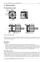
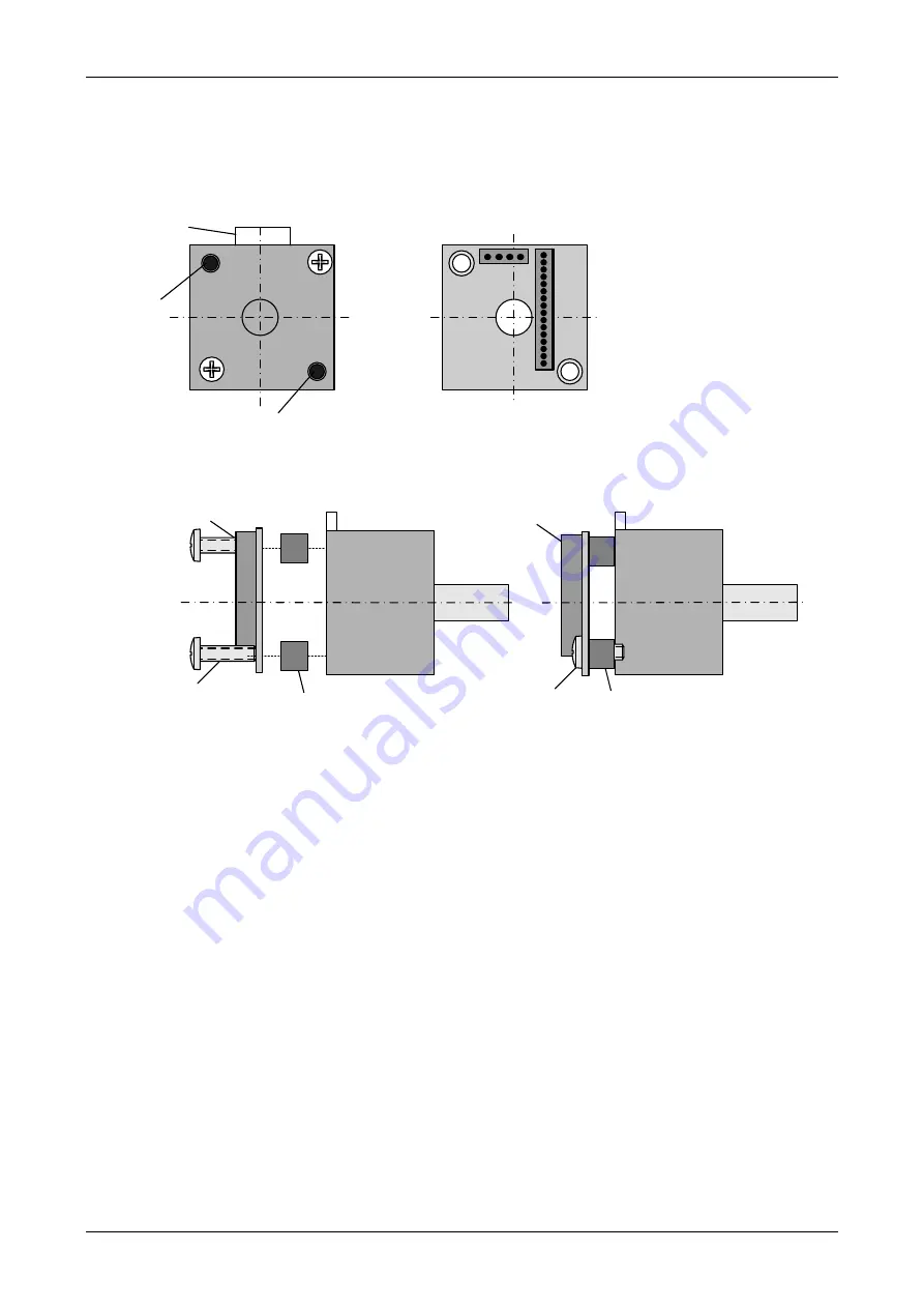
Figure 8.1: Assembly of parts
We recommend a minimum distance between the TMCM-013 and motor of 5mm. The module can be directly
attached to the motor back bell with an electrical insulation spacer. Appropriate cooling might be necessary
if the motor itself gets very hot.
8.2
Motor
Attention:
-
Do not connect or disconnect the motor while power on. Damage to the module may occur.
-
Attention: A too high motor current setting can damage you motor! If in doubt, start with a low current
setting and check motor temperature. If the motor heats up very quickly, check all settings. The motor
shall never reach a temperature above 100°C under any circumstances. Some stepper motors need
contact to metallic parts to allow continuous operation. Mind the default settings when you operate in
step/dir mode the first time. You can store your own settings in the module permanently.
8.2.1
Motor choice
Care has to be taken concerning the selection of motor and supply voltage. In the different chopper modes
different criteria apply. Modes 0 and 1 are quite insensitive to the motor choice, while Mode 2 is very
sensitive, because it uses a different motor current regulation scheme. This chapter gives some
mathematical information on the motor choice, but you can skip it if you want to experiment with a given
motor. Normally, best results will be achieved when operating the given motor in a range of 50 to 100% of
nominal motor current (see motor data sheet). Mode 2 and mode 1 are mainly intended for slow, smooth

