PD-013-42 / TMCM-110-42 Manual (V1.24/2011-NOV-25)
18
Copyright © 2011, TRINAMIC Motion Control GmbH & Co. KG
7.4
Step/direction
Additional Parameters can be set by RS485 i.e. to set a maximum velocity or microsteps per round. The high
levels of the step / direction signals have to be as high as the voltage at V
COM
. For 5V signals e.g. generated
by the TMCM-302 V
COM
has to be 5V also. The step / direction high signal can be up to 24V with matched
voltage at V
COM
.
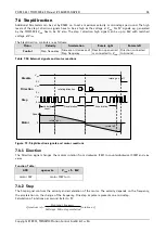
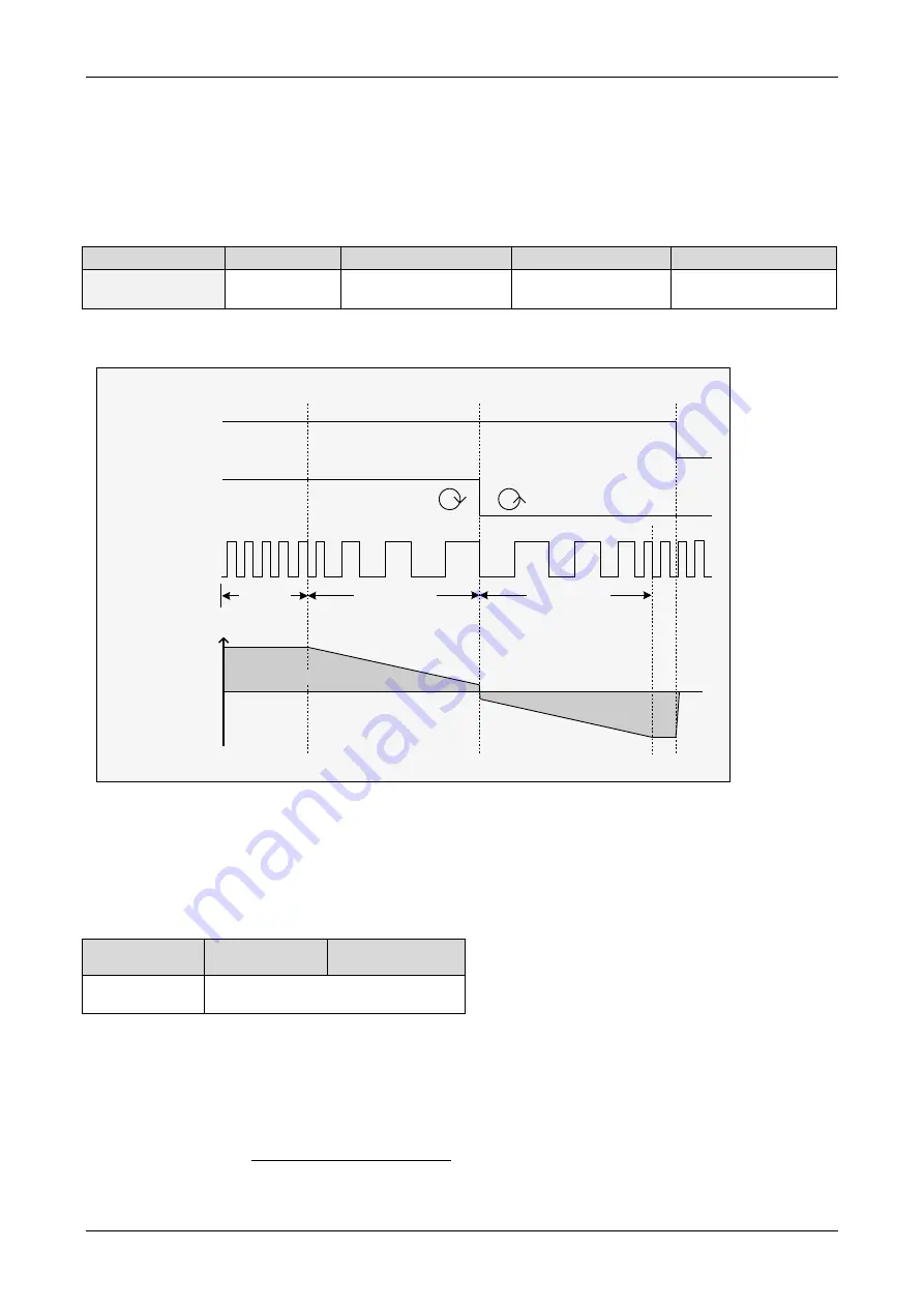
The Step/direction controls are as follows:
Motor
Velocity
Acceleration
Rotate right
Rotate left
Control
Step frequency
Increase or decrease of
Step frequency
Direction open wired
or connected to V
COM
Direction connected
to Ground
Table 7.12: External signals and motor reactions
Motor
Speed
Step
V
com
0 V
Disable
V
com
0 V
Velocity Deceleration Acceleration
rotating on off
const.
Direction
V
com
0 V
rotating direction
rotate left
rotate right
0
Figure 7.3: Step/direction signals and motor reactions
7.4.1
Direction
The Direction signal changes the motors rotation from clockwise (CW) to counterclockwise (CCW) and vice
versa.
Function Table:
GND
open wire
V
COM
= 5… 24V
motor CW
motor CCW turn
7.4.2
Step
The Step signal controls the velocity and acceleration of the motor. The velocity depends on the frequency,
the acceleration on the change of the frequency. One step impulse represents one microstep.
Calculation of rotations per second (refer to 0):
]
/
[
]
/
[
s
rotations
resolution
Microstep
Fullsteps
frequency
input
Step
s
rotations
v


