PD-013-42 / TMCM-110-42 Manual (V1.24/2011-NOV-25)
6
Copyright © 2011, TRINAMIC Motion Control GmbH & Co. KG
4
Electrical and mechanical interfacing
4.1
Pinning
TMCM - 013
TMCM -013 LA
Motor connection
O
A
1
O
A
2
O
B
1
O
B
2
Pin 16
Pin 15
Pin 14
Pin 13
Pin 12
Pin 11
Pin 10
Pin 09
Pin 08
Pin 07
Pin 06
Pin 05
Pin 04
Pin 03
Pin 02
Pin 01
RS 485B
RS 485A
GND
REF B
+ 5 V
REF A
GND
GPI
GPO
Alert
Step
Direction
Disable
GND
VS = 7 ... 28V
Motor connection
O
A
1
O
A
2
O
B
1
O
B
2
U
= 5 ... 24V
common
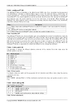
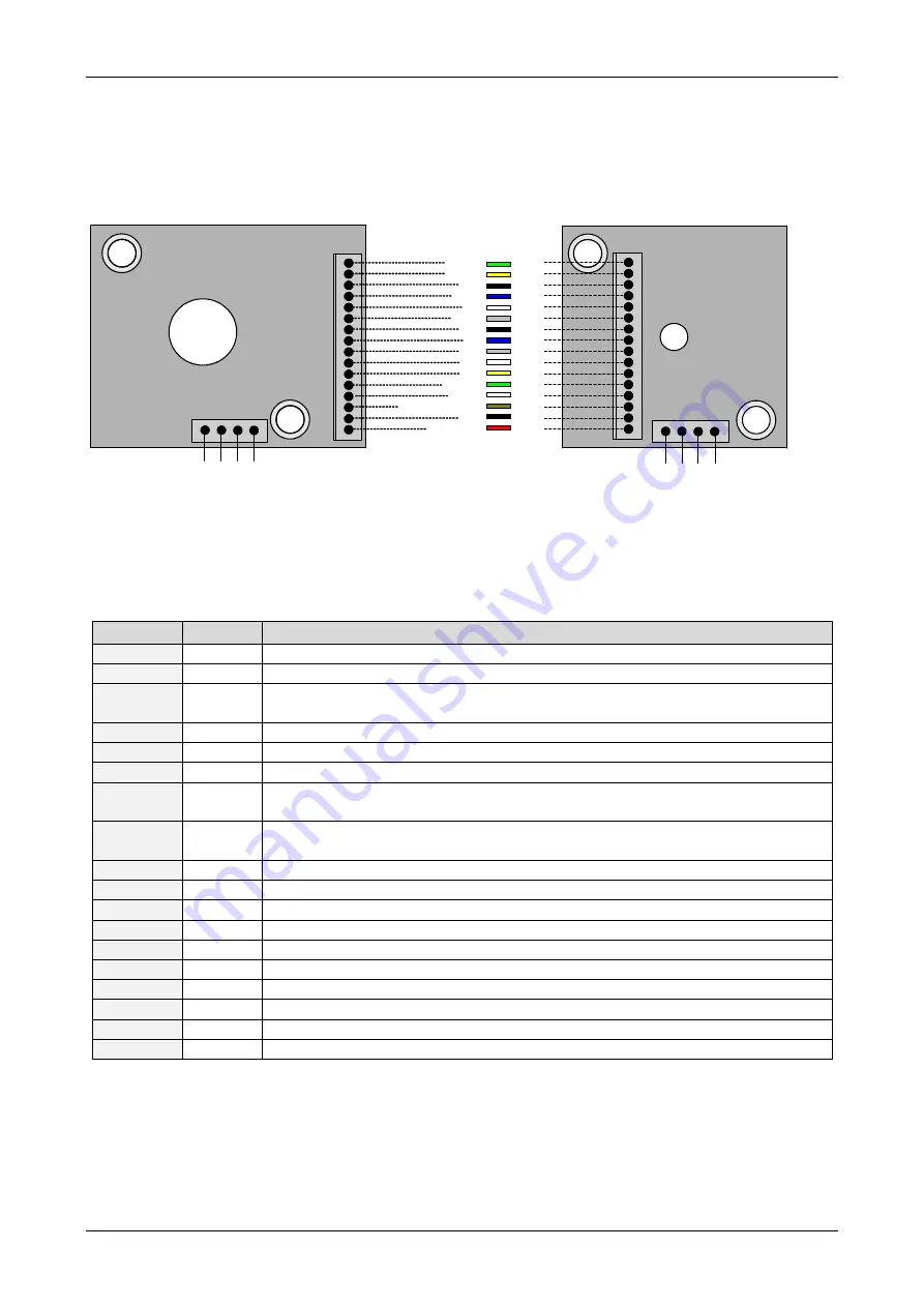
Figure 4.1: Pinning of TMCM-013 and TMCM-013-LA
The numbering printed on the 16 pin connector is reversed. Pin number 1 can be identified by the red
cable for power supply.
Pin
Number
Function
VS
1
Positive power supply voltage
GND
2
GND, power
V
COM
3
Reference voltage for step-direction inputs. Positive optocoupler supply. Required
for negative logic.
Disable
4
Tie to GND to shut down motor power, leave open or at V
COM
otherwise
Direction
5
Tie to GND to inverse motor direction, leave open or at V
COM
otherwise
Step
6
Step signal, optically isolated (Cathode of optocoupler)
Alert
7
Alert output, for wiring scheme see
GPO
8
General Purpose Output, for wiring scheme see
GPI
9
General Purpose Input
GND
10
GND reference
REF A
11
Reference Signal A
+5V
12
Co5V output, reference
REF B
13
Reference Signal B
GND
14
GND for RS485
RS485 +
15
RS485 remote control , TTL input
RS485 -
16
RS485 remote control access -, TTL input
OA1, OA2
Connections for motor coil A
OB1, OB2
Connections for motor coil B
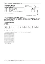
Table 4.1: Pinning of TMCM-013 and TMCM-013-LA


