Version 3.2
Page: 40
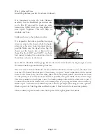
The original Deluxe did not have a standby
switch but one is included in this design and
fits in the original
‘Ground
S
witch’ position.
Another improvement.
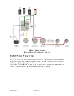
Connect a wire from pin 8 of the rectifier tube to one side of the standby switch. Attach a wire
to the other side of the standby switch that is long enough to route neatly and reach the first
capacitor on the eyelet board, per the layout diagram. Give yourself an extra few inches.
Connect to the center tap of the Output Transformer to the same side of the stand by switch.
For proper voltage mains connections, refer to the Power Transformer schematic.
Once you have wired up the transformer, fuse, stand-by and pilot light socket, it is a good time
to check that the Power transformer is working properly.
Testing the Power Transformer
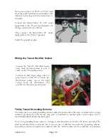
Install the appropriate fuse. Double check that the wiring is as per layout and that the
transformer is wired correctly for your Mains Voltage.
DO NOT INSERT ANY TUBES
. Carefully apply power to the circuit (use Variac if
possible, or current limiting light bulb) and check that the AC voltages are within range of the
spec. Note that they will be higher with NO tubes plugged in.
•
Carefully measure the AC MAINS VOLTAGE
•
Carefully measure the AC VOLTAGE across the INDICATOR lugs. You should
measure around 6.3VAC
•
Carefully measure the AC VOLTAGE across Pins 2-8 of the RECTIFIER SOCKET.
You should measure around 5.0VAC
•
Carefully measure the AC VOLTAGE across Pins 4-6 of the RECTIFIER SOCKET.
You should measure over 700VAC.
If everything measures correctly, then move on to the next step. If not, this is the time to
resolve the issue. If voltages are half what was expected, check the PRIMARY WIRING
matches your local MAINS voltage.
If voltages are very low, check that there are no shorts circuits to ground.
Install the Output Transformer - Output Jacks
Orient the Output Transformer so that the Yellow and Black output (secondary wires) are
closest to the output jacks and Blue, Red and Brown (primary wires) closest to the Power
Summary of Contents for Trinity Tweed Amp
Page 2: ...Version 3 2 Page 2 ...
Page 16: ......
Page 20: ...Version 3 2 Page 20 Input Jack Theory from 18watt com ...
Page 25: ...Version 3 2 Page 25 ...
Page 49: ...Version 3 2 Page 49 ...
Page 65: ...Version 3 2 Page 65 HEYBOER OT for TWEED 6L6GT CONVERSION ...
Page 66: ...Version 3 2 Page 66 ...
Page 75: ...Version 3 2 Page 75 ...
Page 76: ...Version 3 2 Page 76 ...
Page 77: ...Version 3 2 Page 77 Trinity Amps Schematics and Layouts ...

