Version 3.2
Page: 43
Assemble the Eyelet Board
Except for the location of the Phase Inverter resistor network, the layout is based on the
original Fender 5E3 Deluxe. If you do not have a pre-built Trinity amps eyelet board, now is
the time to build it.
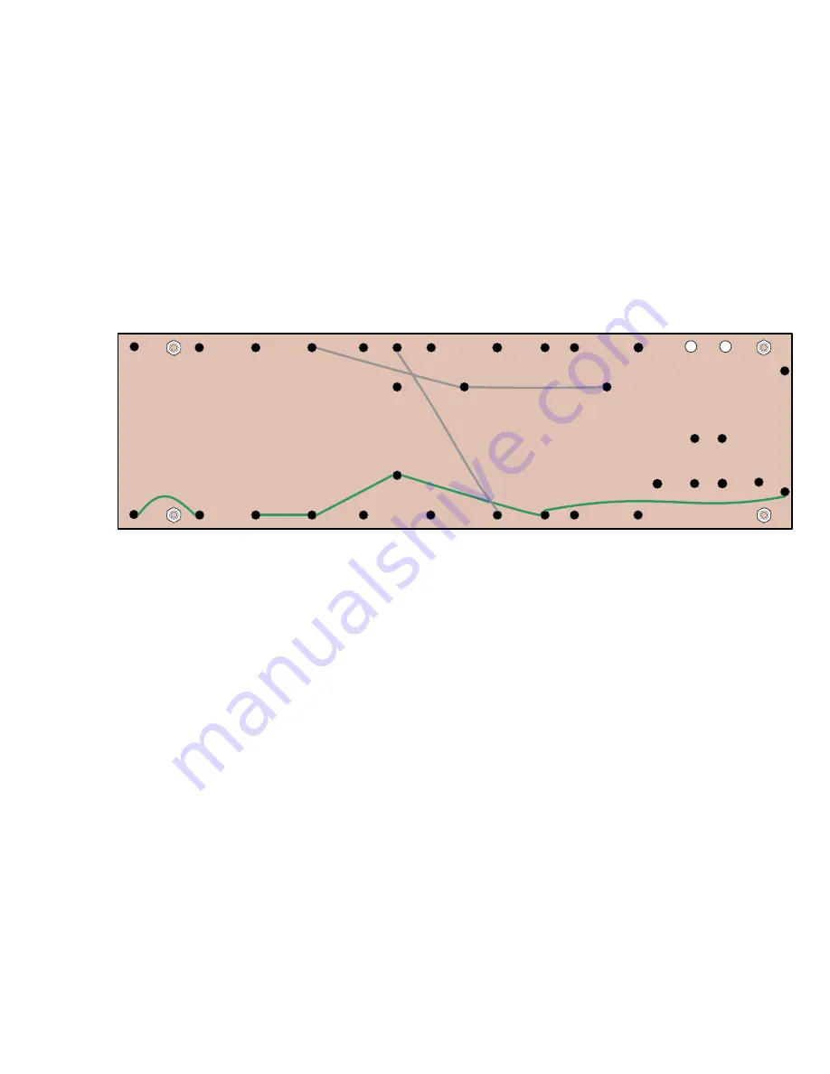
Install the Jumpers
–
Install the jumper wires on the underside of the board. Some leads go
under the board (these are the dashed lines on the supplied layout diagram). Follow the
pictures below and the layout. Do not solder in place yet.
Some builders prefer to run the jumpers on the Top side of the board for ease of future
service. You will have to transpose the layout if you prefer this technique.
Trinity Tweed Board Underside Layout
–
Jumpers Only
Install the Eyelet Board Components
- Align the board according to the layout diagram and
follow the diagram closely as you build the board.
Carefully identify all the board components and their values.
Measure those that you can to
confirm the values.
See the section on how to read Resistor and Capacitor codes.
When installing Electrolytic Capacitors (power supply, bypass caps), ensure that they are
aligned with the correct polarity on th
e board. There may be a ‘+’ sign, or indentation to
identify the positive end of the capacitor or arrows pointing to the negative (ground) end of an
electrolytic capacitor. Usually, capacitors with values less than 1 uF have no polarity
requirements or markings.
Summary of Contents for Trinity Tweed Amp
Page 2: ...Version 3 2 Page 2 ...
Page 16: ......
Page 20: ...Version 3 2 Page 20 Input Jack Theory from 18watt com ...
Page 25: ...Version 3 2 Page 25 ...
Page 49: ...Version 3 2 Page 49 ...
Page 65: ...Version 3 2 Page 65 HEYBOER OT for TWEED 6L6GT CONVERSION ...
Page 66: ...Version 3 2 Page 66 ...
Page 75: ...Version 3 2 Page 75 ...
Page 76: ...Version 3 2 Page 76 ...
Page 77: ...Version 3 2 Page 77 Trinity Amps Schematics and Layouts ...

