Version 3.2
Page: 26
Building an Amp
Warning: Do not attempt to build a guitar amp unless you know how to work safely with the
dangerous voltages present in a tube amp. These voltages can exceed 700 volts.
Introduction
If you have purchased your Trinity Amp as a kit, this guide will help you build a tube guitar
amplifier. It is oriented towards someone who knows a little about electronics but is new to
do-it-yourself amps. It outlines a simple path to getting a quality amp build.
Switches and wire
Use standard UL approved switches with a 125V/3A rating for the Power and Standby
switches. Use 20 or 20 gauge insulated solid wire with a 600V rating. It is good to get a variety
of colors so you can color code your wiring.
Use 18 Gauge stranded for mains wiring.
Physical layout
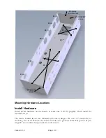
Make sure the jacks, sockets and pots mounted along the edge won't interfere with parts
mounted on the underside of the chassis. Imagine how chassis will be mounted in the cabinet
and make sure there is enough clearance for the speaker and mounting brackets. Trinity amp
chassis are laid out with serviceability and neatness in mind.
Grounding
It is recommended that you follow the layout provided with your Trinity Amp. It has been
tested and has proven reliable. If you choose to deviate, consider the following information.
Amps traditionally use the chassis for signal ground. This is not the best choice since it can
create ground loops and bad ground connections may develop over time. It is better to use star
grounding in which all of the local grounds are collected at a sin
gle ‘star ground’ point. With
star grounding there is only one connection between the chassis and signal ground.
Here are some rules for laying out a star ground. More information on grounding can be found
in the Tube Amp FAQ and the Tech Info page of Aiken Amplification.
(1) Connect the power transformer center tap directly to the negative terminal of the first
power supply filter capacitor (cap) then run a separate wire from the negative terminal to the
star ground point.
(2) Collect the ground points of each tube and its associated resistors and capacitors to a local
ground point that is not connected to the chassis. Run one wire to the star ground point from
each collection.
(3) Run exactly one wire from the star ground point to chassis.
(4) Insulate the input and output jacks from the chassis.
The safety ground wire from the mains is separate from the signal ground. Run a wire from the
AC ground to the chassis near where the AC power enters the chassis.
Summary of Contents for Trinity Tweed Amp
Page 2: ...Version 3 2 Page 2 ...
Page 16: ......
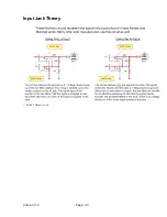
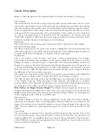
Page 20: ...Version 3 2 Page 20 Input Jack Theory from 18watt com ...
Page 25: ...Version 3 2 Page 25 ...
Page 49: ...Version 3 2 Page 49 ...
Page 65: ...Version 3 2 Page 65 HEYBOER OT for TWEED 6L6GT CONVERSION ...
Page 66: ...Version 3 2 Page 66 ...
Page 75: ...Version 3 2 Page 75 ...
Page 76: ...Version 3 2 Page 76 ...
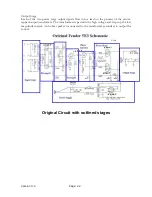
Page 77: ...Version 3 2 Page 77 Trinity Amps Schematics and Layouts ...


