Version 3.2
Page: 71
FAQ
NOTE: B+ stands Battery Plus == B+ and came from the old days of tubes. B+ is measured at the
intersection of the rectifier DC output and the first filter cap.
Q: The pictures show the power and standby switches as "top and bottom" on the back of the switch,
the layout shows them as "front and back" and I have back mounted "left and right". Does it make a
difference as to what orientation I choose to make sure the switch operate correctly, i.e. on is on and
off is off?
A: It does make a difference as to what orientation you choose to make sure the switches operate
correctly. Put a switch in any position and measure the resistance across two terminals. "ON" is where
resistance is zero. Then rotate the switch so that DOWN is ON (UK style).
Q: I assume that the shield is only attached to the pot; it is NOT connected to the tube socket?
A: Yes. Do not connect the shield at both ends on the volume pot OR input cables.
Q: The wire looks to be two basic sizes, "thin" and "thick". From the pictures, it looks like the "thin" is
used for the pot wiring and the "thick" is for the tube sockets. Is this correct?
A:
Use 20 gauge solid for hook up to tubes;
Use 22 gauge, twisted tightly for tube heater wiring;
Use 20 gauge solid/stranded for hook up to pots/front panel; and
Use 18 gauge, stranded, 600v for power supply hook up - to transformers, rectifier, standby etc.
Tip: Re-use cut-offs from the transformers for power supply hook up.
Q: What should I use for the jumper wires on the back of the eyelet board?
A: Use the provided solid 22 ga or the stranded supplied for jumpers, it is not critical.
Q: For the input jacks:
a): I should be using the shielded wire which is the thick gray/black wire that you supplied about 3' of.
Does the shield braid from both lines go to the common tip lug on the lower jack while the core line
goes to the individual tip lugs on both jacks? I want to make sure I am interpreting the drawing
correctly.
b). The other end of the shield does NOT get connected to the tag strip at V1, correct?
c). Each pair of input jacks gets only one resistor, correct? Can I lace one lead of the resistor through
both jacks for the connection?
A: Take a look at the drawing of the input jacks. That should help you out. Use the shielded wire which
is the heavy grey/black wire. The core goes to the hot. At the other end, the shield does NOT get
connected to the tag strip at V1.
Q: Do you need use both of the fiber shoulder washers when mounting the input jacks?
A: Yes, we recommend that you do. Not required for the output jacks
Q: Is there hardware provided for the grounding? Screws, star washers, nuts, etc.?
A: Yes, these should be in the kit.
Note: The power grounds should not go the transformer mount as there is a separate hole to mount the
grounding points.
Summary of Contents for Trinity Tweed Amp
Page 2: ...Version 3 2 Page 2 ...
Page 16: ......
Page 20: ...Version 3 2 Page 20 Input Jack Theory from 18watt com ...
Page 25: ...Version 3 2 Page 25 ...
Page 49: ...Version 3 2 Page 49 ...
Page 65: ...Version 3 2 Page 65 HEYBOER OT for TWEED 6L6GT CONVERSION ...
Page 66: ...Version 3 2 Page 66 ...
Page 75: ...Version 3 2 Page 75 ...
Page 76: ...Version 3 2 Page 76 ...
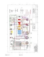
Page 77: ...Version 3 2 Page 77 Trinity Amps Schematics and Layouts ...


