Comfort
BREEZE™
Model CB777
I n s t a l l a t i o n , O p e r a t i o n , & M a i n t e n a n c e M a n u a l
6
www.trioniaq.com
Final installation steps for all mounting locations
•
Install a saddle valve (not provided) on the nearest cold
water supply pipe (see the instructions on the package). If
applicable, connect the saddle valve upstream of any type
of water softener.
•
After the saddle valve has been installed and 1/4” copper
tubing fitted to the valve, but before attaching the copper
tubing to the float and valve assembly, turn the saddle valve
to the open position and discharge the water into a bucket
or pan. This will allow the water to void the line of any debris
that may have accumulated during the installation process.
•
Attach 1/4” copper tubing to the float and valve assembly
with the ferrule and compression nut (provided).
Caution:
The float and valve assembly must not turn when tighten
-
ing the copper tubing compression fittings to the humidifier
water reservoir pan fitting.
•
Turn the water supply on at the saddle valve.
•
Check the water level in the water reservoir pan to ensure
it is 1 to 1 1/2” deep.
IMPORTANT:
In installations where accidental overflow could
cause water damage, connect a drain hose from the
humidifier water reservoir pan overflow tube to a
drain.
Do NOT use a soldered joint because the overflow tube
will become heated and warp the water reservoir pan.
Electrical Installation
WARNING:
Improper electrical wiring can cause personal shock, injury,
or property damage. It is required that the unit be installed
by a properly qualified HVAC technician or electrician,
following NEC and any other local codes.
Electrical installation:
This humidifier is intended to be wired directly to the integrated
control panel on your furnace. The electrical tap will provide
power to the humidifier whenever the circulating air blower is
in operation.
Read the instructions in the furnace installation manual carefully
before attempting installation or operation of this humidifier.
Failure to follow these instructions may result in improper
installation and therefore, void the manufacturer’s warranty.
1. Remove the cover from the junction box in the furnace
jacket.
2.
Connect the humidifier input leads to the two (2) leads that
run to the furnace blower motor. This connection provides
for the automatic operation of the humidifier during the
heating season.
3.
The humidifier will only operate when the furnace blower is
in operation.
4. It is recommended to install the in the system to provide
optimum performance when continuous air circulation is
desired.
5.
If a humidistat is not used in the installation, install an ON/
OFF switch in its place. This provides a simple, yet effective,
method of turning the humidifier off during the summer
months when humidification is not desired.
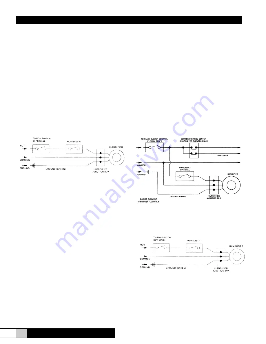
Wiring diagram for humidifier installation - return duct
installation
Furnace wiring connection
Wiring diagram for humidifier installation - free standing
installation
Dedicated wiring connection
=
TO BLOWER
INPUT POWER
INPU
T
POWER
INPU
T
POWER


