ComfortDry CD55 & CD90
I n s t a l l a t i o n , O p e r a t i o n , a n d M a i n t e n a n c e M a n u a l
www.trioniaq.com
5
Step 1: Placement of the Dehumidifier Unit
IMPORTANT: If the dehumidifier unit is handled in
such a manner that the compressor did not remain
in the upright position, it is necessary to place on
a level surface and wait a minimum of two hours
before turning the unit on.
Additionally, ComfortDry dehumidifiers cannot sit
directly on the floor unless the unit condensate drain
output is feeding directly into a sump pump next to it.
When placing, the dehumidifier units are equipped
with adjustable feet that can be used along with a
leveling tool to make sure the dehumidifier rests in
a completely “level” final state as needed for proper
operation.
Step 2: Set Up Drain Line
The condensate drain line should be routed to a
suitable drain to carry the condensate water to the
outside. The drain line must flow down without any
loops, dips, or valleys to the final drain hole.
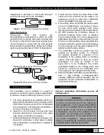
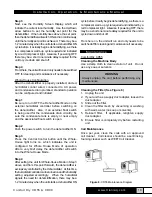
Recommended Dehumidifier Drain Configuration
Including a Transition to PVC Pipe
1. Cut a piece of ¾” OD PVC that is 6” minimum.
2. Insert PVC into a ¾” elbow, then attach a ¾” OD
length of PVC to drain. Keep the length of the
PVC drain pipe to a minimum and make sure it
flows down.
3.
Insert the open end of the dehumidifier
condensate tubing into the ¾” pipe so that it does
not extend into the elbow fitting. For proper flow,
a minimum downward slope of 1” per 10’ run is
required. NOTE: If a proper downward angle is
not possible, then it is recommended to use an
external condensate pump configuration. This
will require expert installation.
4. Support the PVC tubing so that it maintains a
smooth downward flow to drain.
5. Always test the drain before leaving the
installation area.
Step 3: Electrical Power Connections
The dehumidifiers are equipped with a 3-prong,
standard 120VAC electrical plug. Given operation in
damp and wet environments, and to put safety first,
the required electrical outlet to be used to connect
the dehumidifiers should have:
1. Ground Fault Circuit Interrupter (GFCI)
2. 15 Amp minimum circuit that cannot be shared
with any other significant load
120VAC may cause serious injury from electric
shock. To ensure safety:
1. Disconnect electrical power before servicing.
2. Only plug unit into grounded electrical circuit.
3.
Do not use extension cord.
4. Do not use a plug adapter.
Step 4: General Ducting Points and Requirements
In all cases, sound duct design practices must be
followed, such as those provided in ACCA manual “D”
of ASHRAE’s
Fundamentals of Air System Design
.
For supply side air ducting (output from the
dehumidifier), both the ComfortDry CD55 and CD90
have 6” round ducts.
For return side ducting, the dehumidifiers are
equipped as follows:
• A 12” round collar for the CD90.
• The CD55 does not include a return duct, as it is
preferred for standalone operation, which may
not require ducting. However, an 8” round collar
can be ordered separately from TRION and
requires easy mounting.
For ducting material to use between existing ducts
or new ducts with the ComfortDry dehumidifiers, it is
advisable to select an acoustical flex duct material
WARNING
In all cases, local codes precede over installation
and wiring recommendations. Do not plug the
dehumidifiers into the outlet until all the control
circuitry is properly connected.
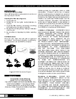
Figure 3.
Drain Tube Drawing


