ComfortDry CD55 & CD90
I n s t a l l a t i o n , O p e r a t i o n , a n d M a i n t e n a n c e M a n u a l
www.trioniaq.com
7
Discussed and illustrated here will be the basic control
scenario for three classes of dehumidifier control:
1.
Standalone unit dehumidification
2.
Whole-house separated dehumidification
3. Whole-house using high integration consolidated
thermostat and humidistat
SUD Configurations
No extra control wiring is required for SUD
configurations, as the ComfortDry dehumidifiers in
this mode operate completely standalone, sampling
humidity from the local air - and then using the settings
made by the user interface to either switch-on or
switch-off. Please reference the Operation section for
details on how to configure and use the ComfortDry
dehumidifier in standalone configurations.
Whole-House Separated Room Configurations
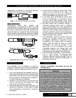
This type can be controlled with the addition of a
single humidistat located in the living area that is
to be served by the ComfortDry dehumidifier. See
Figure 4 below to guide specific hook-ups. For
external control, the dehumidifiers are connected to
the control systems with the 6-position terminal strip
as illustrated.
A1 A2 A3 A4 A5 A6
NORMALLY OPEN FLOAT SWITCH
(PERMANENTLY CLOSES TO DISABLE
DEHUMIDIFIER)
G
*If the dehumidifier is installed in an attic or another location requiring
leak protection, the unit should be placed in a condensate pan with
a normally closed, condensate overflow safety switch (float switch).
Wire the float switch to terminals A5 and A6 as shown.
R
C
DH
DH
HVAC SYSTEM
TERMINALS
EXTERNAL
DEHUMIDISTAT
TERMINALS
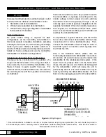
Wiring shows connection of external humidistat to dehumidifier terminals.
Dehumidifier will start HVAC blower upon a call for dehumidification. When
te call is satisfied, the dehumidifier will act to turn off the HVAC blower
unless there is a call for cooling present. At that time, the HVAC
thermostat/air handler will be controlling the HVAC blower.
JUMPER
WIRE
DEHUMIDIFIER TERMINALS
Figure 4.
Wiring Diagram
* If the dehumidifier is installed in an attic or another location requiring leak protection, the unit should be placed in
a condensate pan with a normally closed, condensate overflow safety switch (float switch). Wire the float switch to
Terminals A5 and A6 as shown.
Terminals A3 and A4 need to be powered to switch
the dehumidifier on, typically connecting A4 to the
control voltage common signal (C) and switching
the 24VAC control hot signal (R) through a set of
normally open contacts typically integrated into the
separate humidistat. When the humidity rises above
the set-point, the humidistat contacts close, which
then connects the dehumidifier pin A3 to 24VAC and
switches the dehumidifier ON.
To implement a required interlock with the HVAC
fan control, interconnect dehumidifier terminal strip
connections A3 to A2 as illustrated below. Then,
connect the dehumidifier terminal strip A1 back to
the HVAC “green” connection, which typically turns
the HVAC fan ON.
Also in the illustration below, please note the
functionality associated with dehumidifier connections
A5 and A6. A5 and A6 can be used to interlock the
dehumidifier to the condensate drain system. If the
water does not properly drain and the float switch
closes, this will cause an error function to be triggered
by the dehumidifier, which will cause the unit to
permanently shut off. The error condition can only be
reset by switching the dehumidifier breaker off, then
back on or by unplugging power from the dehumidifier.
Wiring


