background image

Herricane CS

®

 Series

A p p l i c a t i o n   G u i d e

4

www.trioniaq.com

SECTION II SYSTEM OVERVIEW

Why Choose the CS Series?

The CS-Series offers a family of four different products custom sized to handle all of your steam distribution needs. The 

distribution system design has the following features that customers and engineers have told us they desire;

•  Zero Maintenance

• 

Quality Construction - All Stainless Steel, ASME Certified Welds

•  Quality Control - Your unit has been operated prior to shipment

• 

Flexible Design - Works with pressurized boiler, atmospheric boiler, or unfired boiler

•  Capacity to 2000 lbs/hr

• 

Stainless Steel Precision Nozzles

• 

Available “Guaranteed Evaporative Distance” Performance Guarantee

•  Quiet Operation

• 

Superb Energy Efficiency

•  NO FIELD ASSEMBLY of distribution system

• 

Total system design assures that YOU GET THE CAPACITY YOU PAID FOR!

The system is as ingenious as it is simple. In a system with steam supplied be a central boiler, steam flow from the source first 

passes the inlet strainer. From here the steam travels to a condensation trap, and on to the steam valve. Depending on the 

application, this valve could have a solenoid operator, a pneumatic operator, or an electric operator. Once the steam passed 

through the steam valve, or enters the steam distribution system. The steam distribution system utilizes the same nozzle 

design as the original CS-1. This design is extremely quiet, up to 7.3 times quieter than the competition, and efficient, 3-23% 

more efficient than jacketed designs, depending on the duty cycle. Any condensate that forms in the distribution system will 

be disposed of through the manifold trap.

With a self-generating steam unit, the modulation of steam would occur in the boiler itself, therefore, the strainer, steam valve 

and supply trap would be eliminated (See page 24).

Summary of Contents for HERRMIDIFIER Herricane CS Series

Page 1: ...T R I O N w w w t r i o n i a q c o m Herricane CS Series Humidifiers Application Guide ...

Page 2: ...er 15 SECTION III HOW TO SELECT THE PROPER CS SERIES Determine Duct Relative Humidity 17 Determine the Correction Factor for Duct Temperature and RH 18 Determine the Corrected Evaporative Distance 18 Determine the Steam Intensity 19 Choosing the Proper Model and Accessories 20 Steam Valve and Actuator 21 Strainer 21 Traps 21 Control Options 21 SECTION IV PERFORMANCE SPECIFICATIONS Central Steam Co...

Page 3: ... unable to remedy any defects or malfunctions in this humidifier then the user may elect either a replacement of such product or part which may be defective without charge or a refund of the buyer s original purchase price 6 This Warranty gives you specific legal rights and you may also have other rights which vary from state to state NOTE Water quality plays a vital role in the performance and ma...

Page 4: ...gn assures that YOU GET THE CAPACITY YOU PAID FOR The system is as ingenious as it is simple In a system with steam supplied be a central boiler steam flow from the source first passes the inlet strainer From here the steam travels to a condensation trap and on to the steam valve Depending on the application this valve could have a solenoid operator a pneumatic operator or an electric operator Onc...

Page 5: ...oom conditions Steam intensity is defined as the amount of moisture steam introduced per lineal foot of distribution manifold lbm hr ft The first tool is a comparison of evaporative distance under changing conditions of air velocity and steam intensity at standard of 55ºF and 70 downstream relative humidity The second tool developed from thermodynamic and psychrometric relationships and verified w...

Page 6: ...ooling coil Since the cooling coil typically has a drain pan the coil can act as a moisture elimi nator in case something should go awry with the total system control 3 The area prior to the fan or heating coil would be the next choice if sufficient bulk evaporation distance is present If the heating coil is on during periods of humidification the extra heat would help minimize evaporation distanc...

Page 7: ...of these systems include at a minimum a method of distributing steam mounting provisions a steam inlet connection and a condensate drain s connection CS 1100 CS 1102 Steam Distribution Systems Note CS 1100 is designed for Horizontal Airflow CS 1102 is for Vertical Airflow CS 1101 CS 1103 Steam Distribution Systems Note CS 1101 is designed for 1 hose or hose cuff connection CS 1103 includes 2 FPT f...

Page 8: ...oniaq com CS 2105 CS 2106 CS 2107 CS 2108 Steam Distribution Systems Note CS 2105 CS 2106 are designed for Horizontal Airflow CS 2107 CS 2108 are designed for Vertical Airflow CS 3110 Steam Distribution Systems Note CS 3110 is designed for Horizontal Airflow 3 4 ...

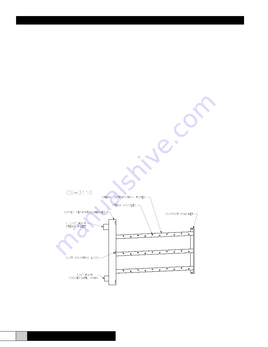
Page 9: ...i o n G u i d e 9 www trioniaq com CS 3113 Steam Distribution Systems Note CS 3113 is designed for Horizontal Airflow SUPPLY SEPARATOR HEADER STEAM DISTRIBUTION TUBES STEAM NOZZLES DUCT MOUNTING LUGS SUPPORT BRACKET 1 1 2 FNPT STEAM INLET ...

Page 10: ...s A p p l i c a t i o n G u i d e 10 www trioniaq com CS 3115 Steam Distribution Systems Note CS 3115 is designed for Horizontal Airflow CS 3119 Steam Distribution Systems Note CS 3119 is designed for Horizontal Airflow ...

Page 11: ...i d e 11 www trioniaq com CS 3112 CS 3117 Steam Distribution Systems Note CS 3112 CS 3117 is designed for Vertical Airflow CS 4111 CS 4116 Steam Distribution Systems Note CS 4111 CS 4116 are designed for Vertical Installation in Horizontal Airflow ...

Page 12: ...Pneumatic ON OFF Electric or Electric Modulating Actuators Inlet Strainer Supply Trap F T Trap or Inverted Bucket Trap Manifold Trap s Angle Thermostatic Trap Vertical Thermostatic Trap or F T Trap Parts Supplied by Others Unions and items shown in dashed lines CS 1100 CS 1102 Steam Distribution Systems CS 2105 CS 2106 CS 2107 CS 2108 Steam Distribution Systems ...

Page 13: ...thers Steam Valve Valve Actuator Pneumatic ON OFF Electric or Electric Modulating Actuators Inlet Strainer Supply Trap F T Trap or Inverted Bucket Trap Manifold Trap s Angle Thermostatic Trap Vertical Thermostatic Trap or F T Trap Parts Supplied by Others Unions and items shown in dashed lines CS 3110 Steam Distribution Systems ...

Page 14: ...Herricane CS Series A p p l i c a t i o n G u i d e 14 www trioniaq com CS 3110 Steam Distribution Systems ...

Page 15: ...rricane CS Series A p p l i c a t i o n G u i d e 15 www trioniaq com Parts Supplied by Others Unions and items shown in dashed lines CS 3115 Steam Distribution Systems CS 3119 Steam Distribution Systems ...

Page 16: ... p l i c a t i o n G u i d e 16 www trioniaq com Parts Supplied by Others Unions and items shown in dashed lines LPR vs Open Gravity Drain CS 3112 CS 3117 Steam Distribution Systems CS 4111 CS 4116 Steam Distribution Systems ...

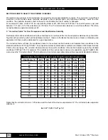
Page 17: ...2 55 12 8 40 51 60 68 77 84 94 60 15 6 36 42 50 56 63 70 77 85 92 65 18 3 30 36 41 50 53 60 66 71 78 82 89 96 70 21 1 25 30 35 40 45 50 56 60 65 70 75 80 72º F 22º C 50 10 50 65 75 85 96 55 12 8 42 54 62 70 80 90 97 60 15 6 37 46 52 60 68 74 81 90 98 65 18 3 30 39 44 50 56 61 70 76 81 88 94 70 21 1 27 31 38 41 48 52 59 54 70 73 80 85 74º F 23º C 50 10 59 69 80 92 55 12 8 49 58 67 78 87 97 60 15 6 ...

Page 18: ...e must be addressed for a good application The correction factor will take the conditions present in the subject duct air handler and translate those conditions to the standard conditions of 55ºF 70 RH The evaporation distances at standard conditions are detailed on the Steam Intensity Chart on the next page The correction factor will make the specific conditions in the duct air handler equal to t...

Page 19: ... fpm Therefore the required steam intensity would be 10 lbm hr ft The highlighted spot shows an evaporative distance of 1 1 at 1500 fpm velocity Steam which would evaporate in 1 1 x 1 25 correction factor or 1 38 at 60 degrees F 80 RH WARNING UTILIZING THE THREE CHARTSABOVE WILLALLOW YOU TOACCURATELY PREDICT THE EVAPORATIVE DISTANCE BASES ON THE DESIGN PARAMETERS YOU SELECT ANY DEVIATION FROM THE ...

Page 20: ...n be achieved with one tube with less than 60 lbs hr capability the CS 1100 is your choice 2 If Tc can be achieved with one tube with less than 500 lbs hr capability the CS 2105 is your choice 3 The CS 3110 has a minimum tube spacing of 3 Therefore the maximum number of tubes is 25 tubes If your total system capacity divided by Tc is less than 25 the CS 3110 may be a possibility It may be possible...

Page 21: ...ected based on valve sizing Special construction such as stainless steel are available upon request Supply Traps Float and Thermostatic or Inverted Bucket supply traps are available Trap sizes are based on inlet pressure and capacity requirements Manifold Traps Float and Thermostatic as well as Thermostatic both angle and vertical are available These are selected based on capacity requirements Con...

Page 22: ...ith silencing media and holes for steam discharge All units were mounted 8 downstream of flow straighteners in 4 x 4 duct section All measurements were taken 1 meter downstream of the manifolds with a Type 1 1 0 dB accuracy SPL meter Air velocity was 500 fpm Results HERRMIDIFIER 78 5 dB Jacketed with Nozzles 94 5 dB Jacketed with Holes 96 0 dB Conclusion The HERRMIDIFIER design including the preci...

Page 23: ...x number of distribution tubes CS 3115 3117 4116 6 28 x length of header in feet 1 70 x length of distribution tube in feet x number of distribution tubes CS 3119 6 28 x length of header in feet 1 83 x length of distribution tube in feet x number of distribution tubes Note CS 1000 and CS 2000 series allow 2 clearance between end of tube and wall CS 3000 and CS 4000 series allow 1 4 clearance betwe...

Page 24: ... heat transfer from the water vapor to the air To calculate the total heat gain to the air humidifier efficiency and air temperature rise use the following two charts and formulas NOMENCLATURE m IN mass flow rate of steam entering humidifier m OUT mass flow rate of steam discharging from humidifier m LIQ mass flow rate of condensate from humidifier f heat gain from humidifier per unit length of ma...

Page 25: ... 609 9 676 6 734 9 787 5 836 1 881 5 924 4 70 533 8 566 6 596 4 661 6 718 6 770 1 817 6 862 0 903 9 75 521 7 553 8 582 9 646 7 702 4 752 7 799 1 842 5 883 5 80 509 6 541 0 569 4 631 7 686 1 735 2 780 6 823 0 863 0 85 497 5 528 1 555 9 616 7 669 8 717 8 762 0 803 4 842 5 90 485 4 515 3 542 3 601 7 653 5 700 3 743 5 783 9 822 0 95 473 3 502 4 528 8 586 7 637 2 682 8 724 9 764 3 801 5 100 461 3 489 7...

Page 26: ...ct height unit mounted completely inside duct x f l 721 6Btu hr ft 3 tubes 5 ft tube 3 ft header x 12 990 Btu hr m LIQ x 966 2 Btu lbmH2 O 12 990 Btu hr 966 2 Btu lbmH2 O m LIQ 13 44 lbmH2 O hr m OUT m IN m LIQ 400 lbmH2 O hr 13 44 lbmH2 O hr m 387 lbmH2 O hr n m OUT m IN 387 lbmH2 O hr 400 lbmH2 O hr n 96 8 s m OUT u 387 lbmH2 O hr 69 8 Btu hr s 27 010 Btu hr h x s 12 990 Btu hr 27 010 Btu hr h 4...

Page 27: ...p not required on CS 1101 CS 1103 or CS 3113 units 3 CS 58 collection header may be used to connect a dual outlet steam tank to a single 2 hose or tube for connection to a distribution system 4 MDD units require a separate distribution system for each cylinder 5 Exact number of steam distributor tubes may vary 6 Exact number of steam nozzles per distributor tube may vary 7 Duct static pressure 5 H...

Page 28: ... shall be pressure tested with steam at operating pressure or greater at the factory prior to shipment 4 Entering steam will be force to take two 90 degree turns before reaching the distribution system pressure systems only 5 The manifold shall be equipped with stainless steel nozzles press fitted into the stainless steel manifold The output of the nozzle is limited to a maximum of 5 lbs hr Exact ...

Page 29: ... analysis design and startup support of the custom engineered humidification system s 2 It shall be the responsibility of the installing contractor to furnish necessary control provisions wiring and plumbing as indicated in the manufacturer s specifications and the appropriate schedules All wiring shall be done in accordance with the applicable sections of electrical specifications and local codes...

Page 30: ... 2018 TRION All Rights Reserved TRION 101 McNeill Rd Sanford NC 27330 P 800 884 0002 F 800 458 2379 www trioniaq com customerservice trioniaq com Form No OM 215 Rev 01 18 ...

Reviews: