background image

23

D01-060en202008 Manual nanoFlu

Use

Malfunction & Maintenance

Commis- sioning

Introduction

General 

Information

FA

Q

Technical Data

W

arranty

Customer

Service

Contact

Keyword 

Index

Accessories

Calibration

nanoFlu 

//


Calibration

All TriOS controllers have the ability to set scaling factors and offset values for the measurement parameters. 

Please refer to the appropriate manual. Make sure not to carry out double scaling with the sensor: once in the 

G2 sensor menu directly and once more with the TriOS controller!
Customer calibration can be used as a fine adjustment of the sensor for special media and is not intended to 

replace the manufacturer calibration.

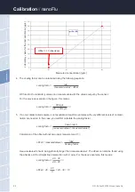
1

2

Laboratory value for the test substance [µg/L]

Measured concentration [µg/L]

Measurement ranges and detection limits of the scaled parameters are dependent 

on the scaling factor!

NOTICE

Summary of Contents for nanoFlu

Page 1: ...nanoFlu OPERATING INSTRUCTIONS ...

Page 2: ......

Page 3: ...e 14 3 2 2 Network 15 4 Use 18 4 1 Normal Operation 18 4 1 1 Immersion Operation 18 4 1 2 Float 18 4 1 3 FlowCell Bypass 19 4 1 4 Cleaning System 19 5 Calibration 20 5 1 Manufacturer Calibration 20 5 2 Customer Calibration 20 6 Malfunction and Maintenance 24 6 1 Cleaning and Upkeep 24 6 1 1 Cleaning the Housing 24 6 1 2 Cleaning the Measuring Window 24 6 1 3 Preparing the Sensor for the Function T...

Page 4: ...operated in accordance with the specifications provided by TriOS Mess und Datentechnik GmbH All parts were designed and tested in accordance with international standards on electronic instruments The device meets the requirements of the international standards on electromagnetic compatibility Please use only original TriOS accessories and cables to ensure smooth and professional use of the devices...

Page 5: ... made between the following cat egories Electromagnetic Waves Devices that radiate strong electromagnetic waves can influence the measurement data or result in a malfunc tion of the sensor Avoid using the following devices in the same room as the TriOS sensor mobile phones cordless phones transmitters receivers and other electrical devices that produce electromagnetic waves Reagents Follow the saf...

Page 6: ...modify a part of the sensor if such a procedure is not explicitly described in this manual Inspections modifications and repairs may only be carried out by the dealer or by qualified experts authorized by TriOS Devices from TriOS Mess und Datentechnik GmbH meet the highest safety standards Repairs to the device which involve the replacement of the connecting cable must be carried out by TriOS Mess...

Page 7: ...sal Instructions At the end of the device s life or use the device and its accessories can be returned to the manufacturer for environmentally friendly disposal for a fee see address below The preceding professional decontamination must be proven with a certificate Please contact us before you send the device back to find out more details Address of the manufacturer TriOS Mess und Datentechnik Gmb...

Page 8: ...tion to the product bar code the rating plate includes the TriOS Mess und Datentechnik GmbH logo and the quality label Please note that the specifications given here are for illustration purposes only and may deviate depending on the version of the product nanoFlu fluorometers are low priced submersible miniaturized fluorometers for highly precise and selective measurement of CDOM colored dissolve...

Page 9: ... of these parts is represented schematically in the above illustration The light source consists of an LED with a defined wavelength depending on the version or parameter The excitation light beam is parallelized and a small part is reflected by a beam splitter short pass onto a ref erence diode to compensate fluctuations in the light source A large part of the light is focused with a lens about 1...

Page 10: ...bond are particularly suitable for fluorescence the electrons are distributed over several atoms and are therefore very easy to excite 2 3 2 Parameters Depending on the parameters nanoFlu uses different LEDs for long term stable measurements of fluorescence values The following parameters see table can be measured or derived with nanoFlu Parameter Excitation wavelength Detection wavelength Chl a 4...

Page 11: ...interface Each line is a link to another page with different setting options The link that refers to the page currently displayed is always highlighted in the menu Special selected contents and functions are exclusively reserved for the employees of TriOS Mess und Datentechnik GmbH Customer Service Authentication is needed for this content The Contents area displays the relevant information and se...

Page 12: ...n of the sen sor Measurement The Measurement page shows the results of the last measurement In addition the interval settings for the automatic measurements and the number of individual measurements to be averaged for the final measure ment can be changed here On this page it is also possible to scale the measured value with the help of entries for Offset and Scaling The new measurement can be tri...

Page 13: ...e previous measurement has not yet been completed after the interval has elapsed e g because the nanoFlu simply needs more time to calculate the average this previous measure ment will be waited out before the next one is started The factory set measurement interval recommended by TriOS Mess und Datentechnik GmbH is 3 seconds If several individual measurements are to be averaged for one measuremen...

Page 14: ...n and follow the safety precautions to protect the sensor from damage and yourself from injury Before the sensor is put into operation it is important to ensure that it is securely attached and all connections are connected correctly 3 1 Electrical Installation 3 1 1 SubConn 8 pin Connector 1 Ground Power Ser Interface 2 RS232 RX RS485 A commands 3 RS232 TX RS485 B data 4 Power 12 24 VDC 5 ETH_RX ...

Page 15: ...nd of the connector into the bulkhead con nection 3 1 2 Fixed Cable with M12 Industrial Plug 1 RS232 RX RS485 A commands 2 RS232 TX RS485 B data 3 ETH_RX 4 ETH_RX 5 ETH_TX 6 ETH_TX 7 Ground Power Ser Interface 8 Power 12 24 VDC Do not twist or bend the connector when plugging or unplugging it Insert the con nector straight in and use the locking sleeve to attach the male contact pin NOTICE Ensure ...

Page 16: ...es of 5 V to 5 V with respect to the ground are possible nanoFlu is delivered as RS 485 in the standard version Upon delivery the nanoFlu is configured for RS 485 with the following settings Baud rate 9600 bps Data bits 8 Stop bits 1 Parity none Detailed description of the Modbus protocol commands can be found in the annex For the RS 232 data transmission takes place on one line per direction with...

Page 17: ...OS G2 sensors the IEEE 802 3 10BASE T compliant Ethernet interface is used as a universal interface This makes it possible to connect a single sensor or even to build a complex sensor network Network with a single G2 sensor The easiest way to connect to the nanoFlu is with the G2 interface box It serves as both the connection and the power supply for the sensor and can be used with all TriOS G2 se...

Page 18: ...end of the sensor into the M12 socket 2 of the G2 interface box and tighten the screw plug Step 3 Connect the 12 or 24 VDC power supply to the G2 interface box to supply the sensor with power Step 4 Waitatleast3secondsbeforeyouconnectyourEthernetLANcablewithyourEthernet capabledevice and the G2 interface box The web interface can now be accessed with any browser using the following URLs http nanoF...

Page 19: ...ers must be supplied by the user nanoFlu recognizes these automatically and then turns off the internal servers Ask your network administrator for advice on how this can best be implemented in your case The following illustrations show examples of different ways to set up a sensor network G2 sensors G2 interface box a Ethernet capable device with DHCP server b Ethernet capable device a Ethernet sw...

Page 20: ...dium To make a correct measurement the measuring window must be completely immersed and free of air bubbles nanoFlu can also be attached with suitable hydraulic clamps Make sure to use suitable brackets with an inner diameter of 36 mm To protect the housing pipe against excess punctual pressure install the brackets close to the device covers Fitting brackets can be obtained from TriOS When immersi...

Page 21: ...1 3 FlowCell Bypass With the optional flow cell the nanoFlu can be installed as a bypass For this purpose you need the nanoFlu FlowCell Art No 10A090000 and a nanoFlu with a special housing which was especially designed for the operation in the FlowCell Art No 32SX03X10 Together with the flow cell a panel is available on which the nanoFlu and the flow cell can be easily mounted 1 Follow the instru...

Page 22: ... of the sensor is carried out as follows The offset is determined by measuring in ultra pure water free of humic and fulvic acid 18 2 MΩcm water A Raw Offset The scaling factor for each measurement range is determined by using the respective calibration stand ard B A lin with A offset corrected value Raw raw data Offset offset value B concentration of the substance in physical units lin scaling fa...

Page 23: ...on at least two data points i e a laboratory value and a sensor value are required The eas iest way to do this is to use a non contaminated sample and a contaminated sample 1 The non contaminated sample is used to determine the offset To do this immerse the fluorometer in the fluid that is not contaminated In this specific case the signal gives the value of the offset directly for local calibratio...

Page 24: ...ilable at least two samples with very different levels of contami nation are needed In this case you will first calculate the scaling factor scaling factor Calculation of the offset without zero point measurement 1 offset measuredvalue2 measuredvalue2 should be significantly larger than measuredvalue1 The offset can also be found using the abscissa of the straight line intersection with X axis For...

Page 25: ...ent parameters Please refer to the appropriate manual Make sure not to carry out double scaling with the sensor once in the G2 sensor menu directly and once more with the TriOS controller Customer calibration can be used as a fine adjustment of the sensor for special media and is not intended to replace the manufacturer calibration 1 2 Laboratory value for the test substance µg L Measured concentr...

Page 26: ...l cleaning with a sponge may be necessary You should exercise extreme caution to avoid scratching the glass of the optical path In the case of calcification a 10 citric acid solution or acetic acid can be used for cleaning Brownish dirt or spots can be contamination due to iron manganese oxides In this case a 5 oxalic acid solu tion or a 10 ascorbic acid solution can be used to clean the sensor Pl...

Page 27: ... already have been cleaned carefully with a detergent solution and rinsed with ultra pure water Immerse the sensor in the container which has been sufficiently filled with ultra pure water so that the measur ing window is completely immersed in water Never place the sensor on the measuring window The measuring window should be at least 10 cm from the floor Wait 10 15 minutes During this time hidde...

Page 28: ... determination at an ambient temperature of 20 C if at all possible The temperature of the ultra pure water should also be 20 C General Information Do not touch the part of the sensor which has been submerged in the ultra pure water with your hands during the sensor check unless you are wearing gloves Be sure to use highly pure water ultra pure resistance of 18 2 MΩcm or distilled water If impurit...

Page 29: ...save path to the corresponding calibration file in the Recover field Next click on the Upload button to begin the transfer When the process has been successfully completed this will be indicated by a green Success box If the process is not successful a red box will be displayed with an error message The following error messages and warnings are possible File not OK The calibration file could not b...

Page 30: ...A form which you need to fill out completely check and send back to us Customer service will check your form and then give you an RMA number Please attach the document with the number so it is clearly visible on the outside of the return package or write it in large numbers on the packaging This is the only way your return package can be correctly allocated and accepted Please make sure that the s...

Page 31: ...no Reaction time T100 6 s Measurement interval 3 s Housing material Stainless steel 1 4571 1 4404 or titanium 3 7035 Dimensions L x Ø 171 mm x 36 mm Weight stainless steel 0 5 kg titanium 0 4 kg Interface digital Ethernet TCP IP RS 232 or RS 485 Modbus RTU Power con sumption typical 1 W with network 1 6 W Power supply 12 24 VDC 10 Required supervision typically 0 5 hours per month Calibration main...

Page 32: ...Data Technical Data nanoFlu 7 2 Measurement Ranges and Limits of Detection The following table provides an overview of the measurement ranges of various parameters and their limits of detection under laboratory conditions Parameters Unit Measurement range Detection limit Chl_a µg L 0 200 µg L 0 500 µg L 0 2 µg L 1 µg L blue µg L 0 200 µg L 0 500 µg L 0 3 µg L 3 µg L CDOM µg L 0 200 µg L 0 3 µg L ...

Page 33: ...liminary iProperty Status Status Titel iProperty Übersicht Titel 36 171 36 207 Position Material body stainless steel or titanium end caps Polyoxymethylene POM optic optical glass screws stainless steel sealings nitrile butadine rubber NBR 1 1 2 2 3 3 4 4 5 5 6 6 A A B B C C D D Name nanoFlu CHL Kabelverschraubung Date 25 10 2017 Rev NF011705 Note Dimensions in mm Document TriOS Mess und Datentech...

Page 34: ...n valve allows the use of compressed air cleaning for the sensors The TriBox3 also offers various interfac es including an IEEE 802 3 Ethernet interface an IEEE 802 11 b g n interface a USB connection and 6 analog outputs 4 20 mA An integrated relay can be used to trigger alarms or to control external devices Features such as low power consumption a robust aluminium housing and a range of interfac...

Page 35: ... not included in the warranty The warranty is subject to the following conditions The device and all accessories must be installed as described in the corresponding manual and must be operated according to the specifications Damage due to contact with corrosive and damaging substances liquids or gases and damage during transport are not covered by the warranty Damage due to improper handling and u...

Page 36: ... problem with the sensor please contact the TriOS customer service We recommend sending the sensor in for maintenance and calibration every 2 years To do this please request an RMA number from customer service Technical support contacts support trios de Tel 49 0 4402 69670 0 Fax 49 0 4402 69670 20 To help us provide you faster service please send us the sensor ID number by email the last four digi...

Page 37: ...lu Contact 11 Contact We are constantly working to improve our devices Visit our website for news If you have found an error or bug in one of our devices or programs please let us know Customer service support trios de General questions sales sales trios de Website www trios de TriOS Mess und Datentechnik GmbH Bürgermeister Brötje Str 25 D 26180 Rastede Germany Tel 49 0 4402 69670 0 Fax 49 0 4402 ...

Page 38: ...leaning 24 Cleaning System 19 Cleaning the housing 24 Cleaning the measuring window 24 Contact 35 Copyright 2 Customer calibration 20 Customer service 34 D Declaration of conformity 5 Detection limit 30 Dimensions 31 Disposal 5 Diving Operation 18 E Electrical installation 12 Electromagnetic waves 3 F Fastening 19 Fluorescence 8 G G2 interface box 16 H Health and safety information 3 I Intended us...

Page 39: ... 15 Normal operation 18 O Offset 20 Operating requirements 4 P Parameters 8 Product Identification 6 Q R Rating plate 6 Reagents 3 Recovery 27 Recovery Point 27 Returns 28 RMA number 28 S Safety instructions 3 Scaling factor 22 Scope of delivery 6 Software updates 2 Specifications 29 Structure of the sensor 7 SubConn 8 pin Connector 12 T Technical Specifications 29 U User requirements 4 V W Warnin...

Page 40: ...ewith declares conformity of the product TriOS GmbH déclare la conformité du produit Bezeichnung nanoFlu Product name Designation Typ Type Type chl a blue cdom Mit den folgenden Bestimmungen 2014 30 EU EMV Richtlinie With applicable regulations 2011 65 EU RoHS Richtlinie Avec les directives suivantes Angewendete harmonisierte Normen EN 61326 1 2013 Harmonized standards applied EN 55011 2009 A1 201...

Page 41: ...Null terminated ASCII character string Uint16 n n Field of n 16 bit integers cf Uint16 Float n 2n Field of n floating point numbers cf float Modbus RTU Data types n 2 Functions nanoFlu supports the following Modbus functions Name Code Description Use Read multiple registers 0x03 Read the serial number configuration calibration and measurement data Write multiple registers 0x10 Write the configurat...

Page 42: ...e Adjustable range 1s 86400s Moving average RW 103 Uint16 Number of individual measurements which are averaged for a measurement Adjustable range 1 25 System date and time RW 104 Uint32 Date and time as seconds since 1 January 1998 Starts again after each power up Device description RW 106 Char 64 An unrestricted description of the sensor e g south supply line Parameter Index for offset scaling RW...

Page 43: ...des the sensor designation followed by the serial number followed by the firmware version each as a null terminated ASCII character string Example n a n o F l u 0x00 D 2 0 0 0x00 1 0 0 0x00 Writing to the configuration registers should be done as seldom as possible and especially not in every measuring cycle otherwise the flash memory may be damaged NOTICE Parametername RW 603 Char 32 Name of the ...

Reviews: