background image

1

Product 

//


Chapter

TABLE OF CONTENTS

Table of Contents

1 General Information

2

1.1  Introduction

2

1.2  Health and Safety Information

3

1.3  Warnings

4

1.4  User- and Operating Requirements

4

1.5  Intended Use

4

1.6  Disposal Information

5

1.7  Certificates and Approvals

5

2 Introduction

6

2.1  Product Identification

6

2.2  Scope of Delivery

7

2.3  Product Structure

7

2.4  Control Elements

8

2.4.1  Display

8

2.4.2  Status LED

8

3 Commissioning

9

3.1  Power Supply

9

3.2  Sensor interfaces

9

3.3  Outputs

10

3.4  Menu

10

3.4.1  Main Menu

10

3.4.2  Sensor

11

3.4.3  Display

11

3.4.4  Options

14

3.4.5  Data

17

3.4.6  Info

17

3.4.7  Power and Home

18

4 Use

19

4.1  Mounting

20

4.2  Electrical Installation

23

4.2.1  Operation with AC Voltage

23

4.2.2  Operation with DC Voltage

25

4.2.3  Prioritized Supply Voltage

26

4.3  Connection of the Sensors

27

4.3.1  Moving Average

32

4.3.2  Smoothing

33

4.3.3  Warning Levels

34

4.4  Calibration Wizard

34

4.5  Installation of Compressed Air Flushing

37

4.6  Data Storage

39

4.7  Recovery

41

5 Advanced Use

42

5.1  Data Export

42

5.2  Analog Output

43

5.3  Relay and Buzzer

46

5.4  Modbus RTU

50

5.5  Network

53

5.6  External Trigger

55

6 Malfunction and Maintenance

56

6.1  Cleaning and Upkeep

56

6.1.1  Cleaning the Enclosure

56

6.1.2  Manual Sensor Cleaning

56

6.2  Maintenance and Inspection

56

6.2.1  Service mode

56

6.2.2  Checking the Analog Outputs

57

6.2.3  Checking the Valve

58

6.2.4  Checking the Relay

58

6.2.5  Working on the Compressed Air System

59

6.2.6  Replacing a sensor

59

6.3  Troubleshooting

60

6.3.1 Changing the Fuse

60

6.3.2  Measuring the Output Voltage

62

6.3.3  Sensor is not displayed

63

6.3.4  Calling up the Recovery Point

65

6.3.5  Modbus Server Problems

66

6.3.6  Support Info

67

6.3.7  Software Update

67

6.4  Return

68

7 Technical Data

69

7.1  Technical Specifications

69

7.2  External Dimensions

71

8 Accessories

72

8.1  AirShot2

72

8.2  Modbus Distributor Box

72

8.3  Compass

72

8.4  TAMMO / AdamE

72

9 Warranty

73

10 Customer Service

74

11 Contact

75

12 Keyword Index

76

13 FAQ - Frequently Asked Questions

78

Annex

82

Summary of Contents for TriBox3

Page 1: ...TriBox3 OPERATING INSTRUCTIONS...

Page 2: ......

Page 3: ...4 5 Installation of Compressed Air Flushing 37 4 6 Data Storage 39 4 7 Recovery 41 5 Advanced Use 42 5 1 Data Export 42 5 2 Analog Output 43 5 3 Relay and Buzzer 46 5 4 Modbus RTU 50 5 5 Network 53 5...

Page 4: ...tion will not be covered by the warranty All sensors and accessories supplied by TriOS Mess und Datentechnik GmbH must be installed and operated in accordance with the specifications provided by TriOS...

Page 5: ...tegories Electromagnetic Waves Devices that radiate strong electromagnetic waves can influence the measurement data or result in a malfunc tion of the sensor Avoid using the following devices in the s...

Page 6: ...nly be carried out by the dealer or by qualified experts authorized by TriOS Devices from TriOS Mess und Datentechnik GmbH meet the highest safety standards Repairs to the device must be carried out b...

Page 7: ...nvironmentally friendly disposal see address below Please contact us for more details before you send the device back Address of manufacturer TriOS Mess und Datentechnik GmbH B rgermeister Br tje Str...

Page 8: ...ger compressed air cleaning in combination with a compressed air source In combination with the nano coated glass panes in most optical sensors made by TriOS Mess und Datentech nik GmbH this makes for...

Page 9: ...product bar code the rating plate includes the TriOS Mess und Datentechnik GmbH logo and the quality label Please note that the specifications given here are for illustration purposes only and may dev...

Page 10: ...al touch pen The main screen as well as the fixed control elements to the right and above can be configured individually The measurement values spectra and the device configuration of the TriBox3 can...

Page 11: ...The TriBox3 requires a secure power supply within the voltage range of 100 VAC to 240 VAC with a mains frequency of 50 Hz to 60 Hz The power supply must be secured according to the local safety stand...

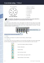
Page 12: ...S 485 B 3 not connected 4 not connected 5 not connected 6 12 VDC 7 GROUND 8 24 VDC 3 4 Menu After installation the TriBox3 can be switched on by switching on the power supply 3 4 1 Main Menu The main...

Page 13: ...nized by the TriBox3 the Sensor submenu displays the following If a sensor is connected and is not shown on a COM port a device search of all COM ports is initiated by press ing on the Scan for Sensor...

Page 14: ...s Commis sioning Commissioning TriBox3 Change the position of a selected display in the entire order For example select Sample values and then press the arrow up to move this display in the entire ord...

Page 15: ...oning current value current measurement value as a number scaled value time variation curve representation of the measurement value over time spectrum for spectral probes representation of the measure...

Page 16: ...ow 3 4 4 Options The Options button opens a submenu that allows you to set general settings define measure ment and cleaning intervals control the relay and buzzer and configure the analog outputs Ser...

Page 17: ...urements allows configuration of the automatic measurements To make use of an automatic measurement interval this must first be activated by checking the box and setting a measurement interval For aut...

Page 18: ...s the user to define the cleaning intervals Relay control The subitem Relay control is dealt with in chapter 5 3 Buzzer control The subitem Buzzer control is dealt with in chapter 5 3 Analog outputs T...

Page 19: ...ioning TriBox3 Commissioning 3 4 5 Data For more information on the menu item Data please see chapter 5 1 3 4 6 Info The Info button opens a window with system information messages and the contact dat...

Page 20: ...ton is only visible as long as the configuration menus are open By pressing this button the configuration menus are closed and only the displays are still visible The System Info menu appears automati...

Page 21: ...safety and VDE regulations must be observed The device may only be opened when the power supply is disconnected Risk of death due to electric shock A fault current circuit breaker with a maximum ignit...

Page 22: ...device 1 To mount the device carefully remove the aluminium panels on both sides of the TriBox3 see figure 2 The device will be attached downward with the connection sockets To ensure the IP protecti...

Page 23: ...and the dimensions of the mounting holes bottom 3 3 4 4 5 5 6 6 A B C D Nam e TriBox3 Date 22 09 2014 Rev TD011 403 Note Dim ensions in m m 2014 1 1 12 TriOS M ess und Datentechnik Gm fon 49 4402 69...

Page 24: ...0 A 5 Fase entfernt 09 07 2015 Witte Freig iProperties bersicht Kommentare im Modell Weitergabe sowie Vervielf ltigung dieses Dokuments Verwertung und Mitteilung seines Inhalts sind verboten soweit ni...

Page 25: ...carefully open the cover of the housing upwards The housing cover must be able to be opened without resistance and without the use of force otherwise there is a risk of damaging the wires in the devic...

Page 26: ...ice 7 Connect the power line to the CON1 plug The following table describes the contact assignment 8 Reconnect the plug to the circuit board and tighten the nut of the cable bushing 9 Check the ground...

Page 27: ...w these steps To open the box and to attach a suitable cable to the TriBox3 please proceed as follows 1 Carefully remove the aluminium panels on both sides of the device 2 Remove the four screws on th...

Page 28: ...now be put into operation 4 2 3 Prioritized Supply Voltage The TriBox3 can be operated with AC or DC voltage The TriBox3 automatically chooses the power supply with the highest priority from the avail...

Page 29: ...technik GmbH may be used to connect the sensors Connect the cable of your TriOS sensor to a COM port on the TriBox3 Insert the M12 connector plug into the desired COM port and secure the connection by...

Page 30: ...3 The settings menu opens by clicking on the COM port button Standard settings of the COM ports for all Modbus capable sensors Protocol Modbus Hardware mode RS 485 Baud rate 9600 Flow control None set...

Page 31: ...n opens like the one in the following example In this screen the current measured value can be seen at the top left and the log protocol of the sensor below that On the right side a description of the...

Page 32: ...eral Information FAQ Technical Data Warranty Customer Service Contact Keyword Index Accessories Use Use TriBox3 The following screen sample illustration opens when the Parameter button has been clicke...

Page 33: ...an be entered here Scaling Here a scaling can be activated and an offset and scaling factor can be entered Please refer to the manual of the respective sensor Moving Average Subitem Moving Average is...

Page 34: ...0 300 400 500 600 700 0 800 900 1000 4 3 1 Moving Average It is possible to output a moving average of the past measurements You can select a period from 30 seconds up to one hour However it should be...

Page 35: ...from the previous measured value The function can be activated for each measured value on the Tribox whereby a maximum signal change of 1 to 999 percent of the previous measured value can be configur...

Page 36: ...ther down you will find the setting options for warning levels In Warning levels the display field of the relevant parameter is lit with a colored background corresponding to the chosen threshold valu...

Page 37: ...ical Data Warranty Customer Service Contact Keyword Index Accessories Use TriBox3 Use 1 Switch to service mode Options menu Maintenance mode button at the bottom of the screen As soon as the service m...

Page 38: ...the type of sensor After selecting the value to be calibrated the calibration wizard starts The respective reference standards should already be available or prepared for calibration e g TpH D refere...

Page 39: ...the end of the hose into the compressed air inlet of the device and check that it is firmly seated by pulling To remove the hose press the small blue safety ring on the compressed air inlet in the dir...

Page 40: ...the valve and the relay are activated during cleaning When the valve switches the air must come out of the outlet and stop completely when the switching procedure has finished If air is not released...

Page 41: ...ord Index Accessories Use TriBox3 Use Recommendations for timer and cleaning intervals Measurement interval Cleaning interval Cleaning time Pause before mea surement minimum 30 s 30 s 5 s 5 s typical...

Page 42: ...s for the individual sensor should be stored Comment This allows a comment to be individually configured for the sensor which is written to the measured values Interval An individual storage interval...

Page 43: ...tings at a later point in time In this illustration a recovery point has already been saved in addition to the factory settings When the device is reset to the factory settings all user specific setti...

Page 44: ...he start datum is copied to the USB stick Use end date All data up to the end date is copied to the USB stick Include spectra in export If using spectral probes this allows the spectra to also be copi...

Page 45: ...n is only active when a data storage device is inserted in the device Always deacti vate this window when removing the USB stick to avoid losing any data Suitable USB sticks that do not affect the IP...

Page 46: ...ur screws on the edge of the TriBox3 with a Phillips screwdriver Please note that only passive components are connected to the analog outputs so that no external voltage can enter This could damage th...

Page 47: ...he control cable to the plug marked in the above illustration The following tables describe the contact assignment CON9 connector Analog outputs 1 4 Pin Assignment 1 Analog output 1 plus 2 Analog outp...

Page 48: ...e following instructions 1 Remove the plug marked CON3 in the illustration and connect to the control line The pin assignment is described in the following table CON10 connector Analog outputs 5 6 Pin...

Page 49: ...at influences the relay trigger and its activation and deactivation limit Plug for relay change over contact Cable bushing for relay CON3 connector Relay changeover contact Pin Assignment 1 Normally c...

Page 50: ...n202111 Manual TriBox3 Use Malfunction Maintenance Commis sioning Introduction General Information FAQ Technical Data Warranty Customer Service Contact Keyword Index Accessories Advanced Use Advanced...

Page 51: ...l Data Warranty Customer Service Contact Keyword Index Accessories Advanced Use TriBox3 Advanced Use Clicking the checkmark in the subitem Buzzer control activates a routine that is configured in the...

Page 52: ...Keyword Index Accessories Advanced Use Advanced Use TriBox3 5 4 Modbus RTU It is also possible to operate each COM port of the Tribox3 in such a way that it works in Modbus server mode In this mode Mo...

Page 53: ...act Keyword Index Accessories Advanced Use TriBox3 Advanced Use In contrast to a simple Modbus device the Tribox3 responds at several slave addresses because the connect ed sensors are distributed ove...

Page 54: ...tion FAQ Technical Data Warranty Customer Service Contact Keyword Index Accessories Advanced Use Advanced Use TriBox3 The Tribox3 also responds to Modbus TCP commands that it receives via the network...

Page 55: ...iBox3 to connect directly to a PC or a network There are different settings for the TCP IP connection Static IP The data are defined by the user static DHCP server A DHCP server in the Tribox assigns...

Page 56: ...served for private purposes are The TriBox3 IP address must be different from the IP address of the computer If the TriBox3 is integrated into a network it must be unique in the entire network If you...

Page 57: ...or from the external trigger input Cable bushing for the exter nal trigger input CON10 connector External trigger input Pin Assignment 5 Trigger input plus 6 Trigger input minus GND 2 Put the plug bac...

Page 58: ...nt unwanted measurements from being taken automatically when manually cleaning the sensors and thus possibly generating false alarms the TriBox3 should be set to service mode beforehand 6 2 Maintenanc...

Page 59: ...n manually cleaning the sensors and thus potentially generating false alarms the TriBox3 box should be set to service mode beforehand 6 2 2 Checking the Analog Outputs To check the functioning of the...

Page 60: ...ll A clicking sound from the valve should be heard clearly every time it switches see chapter 4 5 To check the functioning of the relay it can be directly controlled via the menu A clicking sound from...

Page 61: ...can also be triggered and defined whether the valve and the relay are activated during cleaning 6 2 6 Replacing a sensor If it is necessary to replace a sensor the following must be observed 1 Switch...

Page 62: ...on please read chapter 6 in full to ensure you have the right information for efficient troubleshooting 6 3 1 Changing the Fuse The Tribox3 uses the following fuses Fuse F1 1A 250V time lag 5x20mm ite...

Page 63: ...Advanced Use Commis sioning Introduction General Information FAQ Technical Data Warranty Customer Service Contact Keyword Index Accessories Malfunction Maintenance TriBox3 Malfunction Maintenance Fuse...

Page 64: ...utput voltage first open the cover of the TriBox Here you can see that each COM port has a connector V V 24 VDC 12 VDC To measure the output voltage a voltmeter can be used to measure a voltage of 24...

Page 65: ...h If the standard settings as shown in chapter 4 3 do not cause the device to be displayed a G2 interface connec tion with the sensor should be established and the sensor settings should be set to the...

Page 66: ...r is also not recognised the fuses of the COM port should be checked The exact procedure for this can be found in chapter 6 3 1 Check power supply With some sensors you can easily check whether the se...

Page 67: ...r your safety a recovery point should always be stored when making changes to settings such as scaling factors analog outputs or measurement intervals In this illustration a recovery point has already...

Page 68: ...the installation of the restore point and with Cancel the process is cancelled The second item in the list illustration is a restore point that has been saved on a USB stick and is only dis played as...

Page 69: ...nce of the possible malfunction To do this export the support information to a USB stick and send this to our customer support along with your first inquiry In the subitem Software Update new versions...

Page 70: ...ckage must first be reported to the customer service You will then receive an RMA form with a number which you need to fill out completely check and send back to us Please write the number assigned to...

Page 71: ...Server RTU yes on each sensor connector Client RTU yes on each sensor connector Parameters Adjustable default 9600 8 N 1 MODBUS TCP Server TCP yes TCP port Adjustable default 502 NETWORK USB Standard...

Page 72: ...ing temperature 10 50 with pre installed mains power cable 5 40 C 14 F to 122 F with pre installed mains power cable 41 104 F Storage temperature 20 70 C 4 F to 158 F Relative air humidity 0 95 not co...

Page 73: ...ly instruction of TriBox3 Weitergabe sowie Vervielf ltigung dieses Dokuments Verwertung und Mitteilung seines Inhalts sind verboten soweit nicht ausdr cklich gestattet Zuwiderhandlungen verpflichten z...

Page 74: ...e controlled directly via the Tri Box 8 2 Modbus Distributor Box 5 input M12 connector This distributor box allows a controller input to be ex panded to allow five inputs allowing significantly more s...

Page 75: ...mables such as light sources are not included in the warranty The warranty is subject to the following conditions The device and all accessories must be installed as described in the corresponding man...

Page 76: ...rvice Customer Service TriBox3 10 Customer Service If you are having a problem with the sensor please contact the TriOS technical support Technical support contact support trios de Telephone 49 0 4402...

Page 77: ...ontact 11 Contact We are constantly working to improve our devices Visit our website for news If you have found an error or bug in one of our devices or programs please let us know Technical support s...

Page 78: ...2 Certificates approvals 5 Changing the Fuse 60 Cleaning 56 Cleaning the Enclosure 56 Compressed air cleaning 37 Connection of the Sensors 27 Contact 75 Control Elements 10 Copyright 2 Customer Servic...

Page 79: ...requirements 4 Options 14 Outputs 10 P Panel dimensions 22 Power 18 Power Supply 9 Product Identification 6 Q R Rating plate 6 Recovery 41 Relay 46 Relay control 46 Reset 29 Return 68 RMA number 68 S...

Page 80: ...rs in conjunction with the TriBox3 Before connecting the RAMSES to the TriBox3 the following files must be imported onto the TriBox3 Cal_SAM_8XXX dat CalAQ_SAM_8XXX dat SAM_8XXX ini Back_SAM_8XXX dat...

Page 81: ...ors are now displayed To change the sensor settings click on the button corresponding to the sensor 3 How do I connect an enviroFlu sensor Connect the sensor cable to the TriBox3 Now click on the corr...

Page 82: ...nected to the TriBox3 and displayed with the corresponding parameters in the Sensor menu These are the currently connected sensors which are ready for measurement If the slave ID of the sensor is to b...

Page 83: ...ntact Keyword Index Accessories FAQ TriBox3 FAQ Step 2 Connect a USB stick to the TriBox3 and open the Data menu On the left side is the blue Support Information button Pressing this button opens a su...

Page 84: ...x3 Typ Type Type Art Nr 10C000000 TriBox3 mit WiFi Art Nr 10C100000 TriBox3 ohne WiFi Art Nr 10C100001 TriBox3 EGCWA Mit den folgenden Bestimmungen With applicable regulations Avec les directives suiv...

Page 85: ...CP Modbus TCP can be used by any device that can establish a TCP connection to the TriBox3 By default the TriBox receives incoming Modbus connections on the standard port 502 but the port number can b...

Page 86: ...dress has been assigned the file ModbusStatus txt can be viewed which is part of the Support Information 5 Data types Name Count Format or Range Boolean 1 False 0 True 0 Int16 1 16 bit integer Range 3...

Page 87: ...r Supported devices Description 1 Sensors TriBox Trigger a measurement For sensors a measurement is triggered on this sensor for the TriBox a measurement for the entire measuring system is triggered 2...

Page 88: ...ollowing table lists the registers used by all sensors with up to 32 measurement parameters Register range Datatype Read Write Description 20 39 Char 40 R Name of the device 80 Int16 R Number of param...

Reviews: