background image

10

Triple Solar assembly instruction PVT heat pump panels UK January 2021

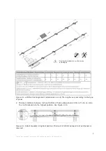
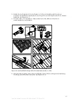
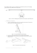
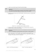
3. Attach the roof brackets to the roof beams or to the roof boarding with the screws 

provided. Use additional underlayment wood to get the correct height and/or for a sturdier 

assembly. See Figure 4.1-c 

4. For some tiles, it is necessary to make a small cut in the bottom of the tiles to 

accommodate the roof brackets. 

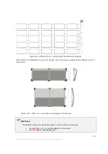
Figure 3.2-c Schuindak montage instructie dakankers (maten in mm)

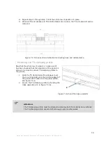
5. Place the first mounting rail on the roof brackets. Secure the mounting rail by tightening 

the flange nut of the cross connector. See Figure 4.1-d. 


Summary of Contents for 101125

Page 1: ...manual heat pump panels triple solar heating without gas...

Page 2: ...stances between rows on pitched roof 7 4 Preparation for pitched roof tiled roof 8 5 Preparing a flat roof 11 6 Preparing a EPDM bitumen roof 12 7 Placing the panels on the mounting rails 13 The TS cl...

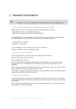
Page 3: ...he panels The heat pump panels are designed for the following allowable loads Pressure load Snow Wind 5400 Pa Tensile load Wind 2400 Pa The mounting material supplied by Triple Solar is T V approved a...

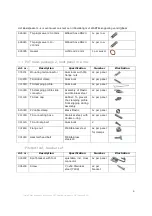
Page 4: ...k 4x per row 310101 TS end clamp Aluminum 4x per row 311000 TS clamping profile Aluminum 1x per panel 310300 TS clamping profile slide connector Plastic and Stainless steel 2x per panel 311130 TS lock...

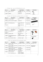
Page 5: ...er panel 311000 TS clamping profile Aluminum 1x per panel 310300 TS clamping profile slide connector Assembly of Plastic and Stainless steel 2x per panel 311130 TS lock cap Rubber To prevent the clamp...

Page 6: ...Art nr Description Specification Number Illustration 890020 890010 Roof gland set Inc collar red or anthracite 1x 890005 Sealing collar EPS diam 50 70mm 1x 425080 TS spigot spigot 1000 2000mm Ribbed h...

Page 7: ...re per PVT panel 800300 Propylene glycol for active cooling Premixed 40 5 litre per PVT panel Art nr Description Specification Number Illustration 430010 Afsluiter 3 4 bi bu 1 500200 Spoel en vul aans...

Page 8: ...position of the roof gland beforehand The greater the distance between the rows the less the shadowing the more electrical output See Figure 3 1 a When considering row spacing also consider walking s...

Page 9: ...h panel is supported by 2 horizontal mounting rails Start assembling at the bottom of the panel field 1 Place the outer roof bracket 450 mm from the edge of the panel field For a 2 meter panel length...

Page 10: ...ngths vary according to the type of panel 2 Minimum distance between roof and bottom of heat pump panels is 90mm To do so slide the roof brackets into the highest position See Figure 4 1 b Figure 4 1...

Page 11: ...d to get the correct height and or for a sturdier assembly See Figure 4 1 c 4 For some tiles it is necessary to make a small cut in the bottom of the tiles to accommodate the roof brackets Figure 3 2...

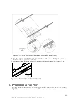
Page 12: ...istance between panels at least 40mm 7 Connect the next mounting rail with the mounting rail interconnector See Figure 4 1 e Figure 3 2 e Pitched roof connecting mounting rails 5 Preparing a flat roof...

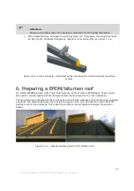
Page 13: ...to the Sunbeam mounting system 6 Preparing a EPDM bitumen roof For pitched EPDM bitumen roofs Triple Solar delivers roof feet with an EPDM layer These can be screwed to vertical wooden beams 50mmx40m...

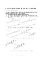
Page 14: ...nnector into the rail and turn it a quarter turn 2 Slide the TS clamping profile over the TS sliding connectors Make sure it is placed in the right direction to fit into the panel profile later 3 Pres...

Page 15: ...lip bolt into a hole in the end profile on each side of the heat pump panel to prevent it from slipping See figure 7 2 a Figure 7 2 a panel with M8 bolt to prevent slipping 2 Lay down the outer heat p...

Page 16: ...e two connecting hoses into the headers until both O rings are no longer visible see figure 7 2 c Figure 7 2 c connecting hoses mounted on one side 6 Carefully push the entire panel sideways in one co...

Page 17: ...anels is in place and it has been checked that the alignment of the panels is correct it is time to connect TS clamping profiles to the panels 1 Slide the TS clamping profile sideways over the mountin...

Page 18: ...over the header of the panels and into the slot in the TS plug spigot ribbed hose See in Figure 7 4 a at D Connecting the PV panels electrically The instruction for the electrical connection of the h...

Page 19: ...mizers It is important to avoid large induction loops in order to ground the PV cables correctly The correct way is to lay the electrical cables next to each other as much as possible see figure 7 5 b...

Page 20: ...Plastic pipes lying in the sun should always be protected against UV light by means of a UV resistant sheath or UV resistant paint The plastic pipes must be suitable for the source fluid Indoors keep...

Page 21: ...on With a flat roof installation in rows of 2 panels the return pipe is always at the highest point of the panels Attention Preferably connect the panel according to the Tichelmann principle connect t...

Page 22: ...meter of the pipes running to and from the panel field 6 kW to 8kW 26 mm inside 8 kW to 15kW 32 mm inside 15kW to 28kW 41 mm inside 28kW to 50kW 51 mm inside Hydraulic plan See the general hydraulic p...

Page 23: ...pump and as close to the pump as possible Attention It is not recommended to use automatic air vents in the source circuit as these become unreliable in the long run when the condensate freezes and m...

Page 24: ...ing the expansion vessel Mounting the expansion vessel In the suction side of the system This is in the warm side of the well see diagram in figure 8 3 a This is different from continuous heating inst...

Page 25: ...event cold bridges Flamco CB cold bridge free pipe support 28mm 39888 Figure 8 7 a Flamco support preventing cold bridges Micro air bubble separator Installing a micro air bubble separator removes all...

Page 26: ...Slide the tube clamp over the end of the mounting rails Figure 9 1 a Mounting the pipe clamp 3 Reinstall the end clamp in combination with the pipe clamp holder and the mounting rail The cut out shou...

Page 27: ...UK January 2021 Figure 9 1 c Clamping the pipes 5 The cover plate is inserted into the side frame of the panel and is secured on the other side at the end of the pipe clamp by the self tapping screw...

Page 28: ...ail cover by squeezing the sides together Slide the cover over the mounting rail Figure 9 2 a Covering the ends of the mounting rails 10 Activating the system Testing leak tightness filling and system...

Page 29: ...ystem Attention Check the filter of the filling machine and the filter in the pipework Clogging can cause too low a flow Filling and venting After flushing the field is completely filled and pressuriz...

Page 30: ...to UV radiation and lacquer corrosion 5 A removed or illegible type plate Entrance control Please check the delivered products for any damage immediately upon delivery In the case of obvious defects...

Reviews: