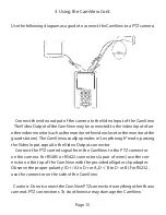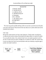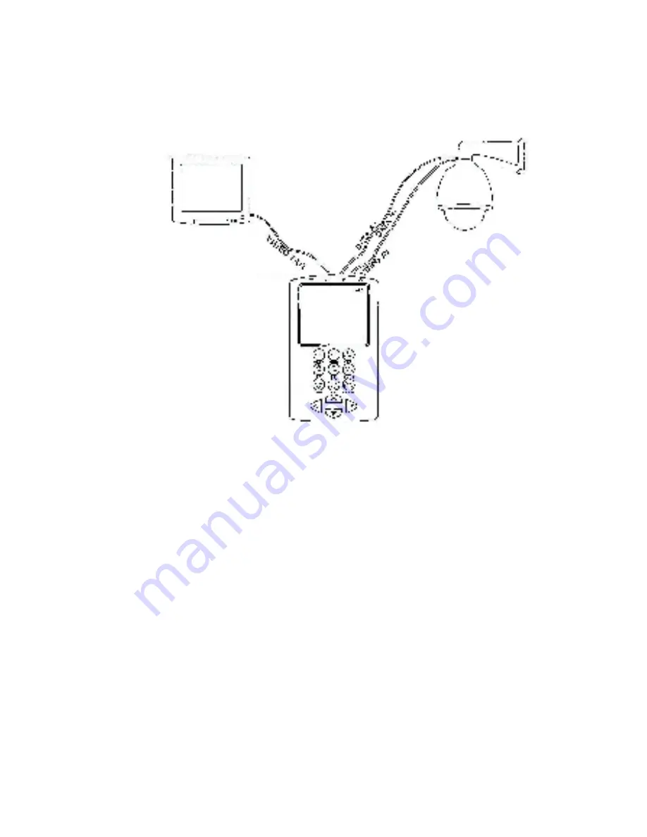
Use the following diagram as a guide to connect the CamView to a PTZ camera.
Page 15
3 Using the CamView Cont.
Connect the video output of the camera to the Video Input of the CamView.
The Video Output of the CamView may be connected to the video input of an-
other video monitor (such as the monitor in the video closet or the monitor at the
guard station). The CamView usually operates in ‘Loopthrough” mode, passing
the Video Input signal to the Video Output connector.
Connect the PTZ control signal from the CamView to the PTZ connector
on the camera. For RS485 or RS422 connectors (a pair of wires) use the con-
nector on the top of the CamView with the provided alligator clip adapter.
Observe the proper polarity (D +/ A to D+ or A, D -/ B to D- or B).For RS232,
use the connector on the side of the CamView.
Caution: Do not connect the CamView PTZ connector to anything other than a
camera’s PTZ connections. To do otherwise may damage the CamView.
Summary of Contents for CamView PTZ 2
Page 1: ...REV A 10 13 CamView PTZ 2 TM Instruction Manual PN 8001 ...
Page 2: ......
Page 10: ...Page 8 2 3 Controls and Indicators 1 2 3 4 5 6 7 8 9 10 11 12 13 14 15 16 17 18 19 20 ...
Page 43: ...Notes ...
Page 44: ......


