4
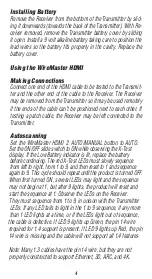
Installing Battery
Remove the Receiver from the bottom of the Transmitter by slid-
ing it downwards (towards the back of the Transmitter). With Re-
ceiver removed, remove the Transmitter battery cover by sliding
it open. Install a 9 volt alkaline battery taking care to position the
lead wires so the battery fits properly in the cavity. Replace the
battery cover.
Using the WireMaster HDMI
Making Connections
Connect one end of the HDMI cable to be tested to the Transmit-
ter and the other end of the cable to the Receiver. The Receiver
may be removed from the Transmitter so it may be used remotely
if the ends of the cable can’t be positioned next to each other. If
testing a patch cable, the Receiver may be left connected to the
Transmitter.
Autoscanning
Set the WireMaster HDMI 2 AUTO/MANUAL button to AUTO.
Set the ON/OFF slide switch to ON while observing the X-Test
display. If the Low Battery indicator is lit, replace the battery
before continuing. The red X-Test LEDs must slowly sequence
from left to right, from 1 to 9, and then reset to 1 and sequence
again to 9. This cycle should repeat until the product is turned OFF.
When first turned ON, several LEDs may light and the sequence
may not begin at 1, but after 9 lights, the product will reset and
start the sequence at 1. Observe the LEDs on the Receiver.
They must sequence from 1 to 9, in unison with the Transmitter
LEDs. If any LED fails to light in the 1 to 9 sequence, if any more
than 1 LED lights at a time, or if the LEDs light out of sequence,
the cable is defective. If LED 9 lights up Green, the pin 14 wire
required for 1.4 support is present. If LED 9 lights up Red, the pin
14 wire is missing and the cable will not support all 1.4 features
Note: Many 1.3 cables have the pin 14 wire, but they are not
properly constructed to support Ethernet, 3D, ARC, and 4K.


