background image

7

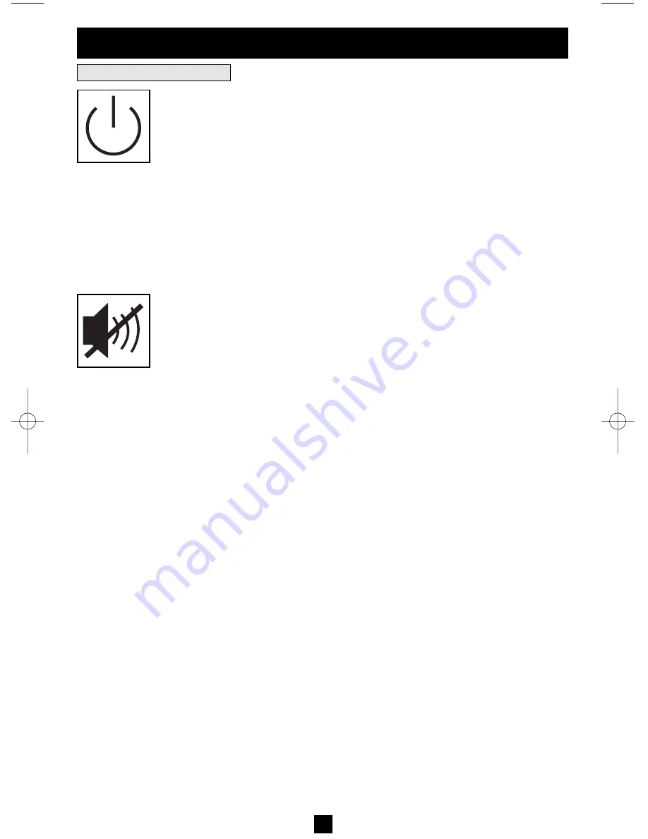
“ON/OFF/STANDBY” 

Button

• To turn the UPS ON:

with the UPS plugged into a live AC wall outlet*, press

and hold the “ON/OFF/STANDBY” button for one second.** Release the but-
ton. If utility power is absent, you can “cold-start” the UPS (i.e.: turn it ON and
supply power for a limited time from its batteries***) by pressing and holding
the “ON/OFF/STANDBY” button for one second.**

• To turn the UPS OFF:

with the UPS ON and receiving utility power, press and

hold the “ON/OFF/STANDBY” button for one second.** Then unplug the UPS
from the wall outlet. The UPS will be completely OFF.

* After you plug the UPS into a live AC outlet, the UPS (in ”Standby” mode) will automatically charge
its batteries, but will not supply power to its outlets until it is turned ON. ** The alarm will beep once
briefly after the indicated interval has passed. *** If fully charged.

“MUTE/TEST”

Button

To Silence (or “Mute”) UPS Alarms:

briefly press and release the MUTE/TEST

button.*

To Run a Self-Test:

with your UPS plugged in and turned ON, press and hold

the MUTE/TEST button for two seconds.* Continue holding the button until
the alarm beeps several times and the UPS performs a self test. See “Results of
a Self-Test” below. Note: you can leave connected equipment on during a self-test.
Your UPS, however, will not perform a self-test if the UPS is not turned on (see
“ON/OFF/STANDBY” Button description).

CAUTION! Do not unplug your UPS to test its batteries. This will remove
safe electrical grounding and may introduce a damaging surge into your
system connections.

Results of a Self-Test:

The test will last approximately 10 seconds as the

UPS switches to battery to test its load capacity and battery charge. 

• If the “OUTPUT LOAD LEVEL” LED remains lit red and the alarm contin-

ues to sound after the test, the UPS’s outlets are overloaded. To clear the over-
load, unplug some of your equipment and run the self-test repeatedly
until the “OUTPUT LOAD LEVEL” LED is no longer lit red and the
alarm is no longer sounding.

CAUTION! Any overload that is not corrected by the user immediately
following a self-test may cause the UPS to shut down and cease supplying
output power in the event of a blackout or brownout.

• If the “BATTERY WARNING” LED remains lit and the alarm continues

to sound after the test, the UPS batteries need to be recharged or
replaced. Allow the UPS to recharge continuously for 12 hours, and 
repeat the self-test. If the LED remains lit, contact Tripp Lite for service.
If your UPS requires battery replacement, visit www.tripplite.com to
locate the specific Tripp Lite replacement battery for your UPS.

* The alarm will beep once briefly after the indicated interval has passed.

Basic Operation

Buttons (Front Panel)

200507083 93-2477 Sinewave SmartPro Rackmount UPS OM.qxd  10/19/2005  10:35 AM  Page 7

Summary of Contents for 2POSTRMKITWM

Page 1: ...erved Audio Video Automatic Voltage Regulation AVR UPS Systems Intelligent Line Interactive Operation Sine Wave Output 500VA 1500VA Capacities Extended Run Options Except 500VA sine wave output on line PWM output on battery Not suitable for mobile applications Battery Replacement 12 Optional Installation 6 WARRANTY REGISTRATION Register online today for a chance to win a FREE Tripp Lite product ww...

Page 2: ...tions in which a malfunction or failure of a Tripp Lite UPS System could cause failure or significantly alter the performance of a life support device Do not connect surge suppressors or extension cords to the output of your UPS This might overload the UPS and will void the surge suppressor and UPS warranties Battery Warnings Batteries can present a risk of electrical shock and burn from high shor...

Page 3: ... does not include an adjustable rackmount shelf kit skip steps 1 and 2 Connect the two segments of each shelf using the included screws and nuts Leave the screws slightly loose so that the shelves can be adjusted in the next step Adjust each shelf to fit your rack then mount them in the lowest available space of your rack with the screws nuts and washers provided Note that the support ledges shoul...

Page 4: ...r equipment to the rack by passing the screws nuts and washers provided through its mounting ears and into the rack rails D C B A 1 2 B A D C 1 2 Tower Mounting 4 Mount all UPS models in an upright tower position using included hardware The user must deter mine the fitness of hardware and procedures before mounting All UPS Models Stand your UPS on its side with the LED Control panel at the top Att...

Page 5: ...PS is designed to support Media Center PCs home automa tion systems and audio video components only You will overload the UPS if the total VA ratings for all the equipment you connect exceeds the UPS s Output Capacity To find your equipment s VA ratings look on their nameplates If the equipment is listed in amps multiply the num ber of amps by 120 to determine VA Example 1 amp 120 120 VA If you ar...

Page 6: ...ine surge suppressor do not connect a phone line to this port External Battery Connection select models only Your UPS comes with a robust internal battery sys tem external batteries are needed only to extend run time Adding external batteries will increase recharge time as well as runtime The illustration see shows the location of your UPS s External Battery Connector where you will insert the bat...

Page 7: ...PS however will not perform a self test if the UPS is not turned on see ON OFF STANDBY Button description CAUTION Do not unplug your UPS to test its batteries This will remove safe electrical grounding and may introduce a damaging surge into your system connections Results of a Self Test The test will last approximately 10 seconds as the UPS switches to battery to test its load capacity and batter...

Page 8: ...event of a blackout or brownout BATTERY CHARGE LED when the UPS is operating from utility power this LED indicates the approximate charge state of the UPS s internal batteries red indicates the batteries are beginning to charge yellow indicates the batteries are roughly midway through charging and green indicates the batteries are fully charged When the UPS is operating from battery power during a...

Page 9: ...panel which provide surge only not battery backup protection Select models also feature outlets labelled UNSWITCHED which may not be remotely switched off See software instructions for details Communications Ports USB or RS 232 These ports connect your UPS to any Media Center PC or home automation system Use with Tripp Lite s PowerAlert Software and included cables to enable your Media Center PC h...

Page 10: ...st mode so that the effect on the equip ment of any waveform distortions in the UPS s output can be evaluated without disrupting Media Center PC or home automation system operation External Battery Connector Select Models Only Use to connect Tripp Lite external battery packs for additional runtime Refer to instructions available with the battery pack for complete connection information and safety ...

Page 11: ... This is the most common cause of service inquiries which can be easily remedied by following the resetting instructions in this manual 2 If the problem continues do not contact or return the UPS to the dealer Instead call Tripp Lite at 773 869 1233 A service technician will ask for the UPS s model number serial number and purchase date and will attempt to correct the problem over the phone 3 If t...

Page 12: ...rcuit different from that which the receiver is connected consult the dealer or an experienced radio television technician for help The user must use shielded cables and connectors with this product Any changes or modifications to this product not expressly approved by the party responsible for compliance could void the user s authority to operate the equipment This device complies with part 15 of...

Reviews: