background image

9

Battery Connection

1.

Connect your APS’s positive DC Terminal directly to a fuse.

Tripp Lite recommends that you install a recognized component fuse block and fuse within
18 inches of the battery. The fuse's rating must equal or exceed the Minimum DC Fuse
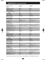
Rating listed in your APS model’s specifications on pages 16 or 17.

2.

Choose a battery configuration appropriate to your batteries.

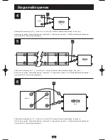
• Single Battery Connection: Refer to Diagram 4, page 37. When using a single battery,

its voltage must be equal to the voltage of your APS’s Inverter Nominal Input Voltage
(see specs).

• Parallel Battery Connection: Refer to Diagram 5, page 37. When using multiple 

batteries in parallel, each battery's voltage must be equal to the voltage of your APS’s
Inverter Nominal Input Voltage (see specs).

• Series Battery Connection: Refer to Diagram 6, page 37. When using multiple batteries

in series, all batteries must be equal in voltage and amp hour capacity, and the sum of
their voltages must be equal to the voltage of your APS's Inverter Nominal Input Voltage
(see specs).

3.

Use 2/0 gauge wire ONLY to make external battery connections. Tighten battery terminals
to a torque of 4 N-m. 

Battery connection cable lengths should be short as possible, and must not exceed the Maximum
Cable Length listed under Specifications, page 16 or 17. Shorter and heavier gauge cabling limits
DC voltage drop and allows for maximum transfer of current.* You must tighten your battery 
terminals to approximately 4 Newton-meters of torque to create an efficient connection and prevent
excessive heating. Insufficiently tightening terminals could void your PowerVerter’s warranty.

* APS models are capable of delivering a much higher wattage output for brief periods of time. Wiring should be 
configured to handle this brief high-current draw. Though your APS is a high-efficiency converter of electricity, its rated
output capacity is limited by the length and gauge of the wires running from the battery to the APS.

APS systems may be permanently mounted in a car, truck or boat and connected to draw power from
the vehicle’s battery. 

Note: An APS can ONLY be connected to vehicle batteries with voltage

that matches the APS’s Nominal DC Input—12V vehicle batteries to 12V Nominal DC
Input APS systems, etc. (See Specifications).

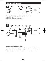
There are two main ways to make this sort of

vehicular battery connection. Choose the Basic Connection if you are running light hand tools or
other small appliances for a brief period of time 

(see Diagram 7, p. 38)

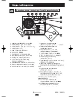
. Choose the Advanced

Connection if you are using your APS to power heavy loads for extended periods of time 

(see

Diagram 8, p. 38).

The Advanced Connection incorporates a battery isolator and separate battery

system to provide battery power to your APS while preventing it from draining your vehicle’s
battery. Note: Depending on your application, you may require more than one Deep Cycle Battery.

Caution: Never operate your APS from an alternator without a battery connected as shown in Diagrams 7 or 8, p. 38.
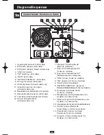
Standard

DC Vehicular

200106010 230V APS Owners Manual.qxd  1/3/02  5:18 PM  Page 9

Summary of Contents for 93-2007 (200106010)

Page 1: ...Instructions 4 Configuration Connection 5 Features 11 Maintenance and Service 14 PowerVerter is a registered trademark of Tripp Lite All rights reserved APS PowerVerter Alternative Power Sources 230V...

Page 2: ...attery charge decreases Automatic Overload Protection If you overload your APS it will automatically protect itself and your valuable batteries from damage Fast Load Switching Your APS provides an uni...

Page 3: ...osting or cutting the voltage to keep your equipment running through brownouts and overvoltages without draining battery power Load Sharing Select models only Select APS models can be set to limit the...

Page 4: ...al battery connection Always observe proper polarity as batteries are connected Do not allow objects to contact the two DC input terminals Do not short or bridge these terminals together Serious injur...

Page 5: ...To Battery Point DIP Switch 2 Group A Voltage Switch Position 264V Up 259V Down Select Low AC Voltage Switch To Battery Point DIP Switches 4 Group A 3 Group A Voltage Switch Postion 201V 4 Up 3 Up 182...

Page 6: ...heir AC load and charger power within their circuit breakers rating This charger limiting function has four settings allowing you to choose less charger limiting for APS configurations with higher rat...

Page 7: ...mit Battery Charger DIP Switch 4 Group B APSINT1524 only To prevent overheating smaller batteries the charger on this UPS system is initially set to deliver only a fraction of its maximum power rating...

Page 8: ...Hour ratings of batteries are usually given for a 20 hour discharge rate Actual Amp Hour capacities are less when batteries are discharged at faster rates batteries discharged in 55 minutes provide o...

Page 9: ...You must tighten your battery terminals to approximately 4 Newton meters of torque to create an efficient connection and prevent excessive heating Insufficiently tightening terminals could void your P...

Page 10: ...ad your wires through strain reliefs and through the knockouts 3 Connect all input and output ground wires to the input output ground tie point 4 Connect the incoming hot wire to the input hot brown t...

Page 11: ...has shut down due to overload or overheating See Diagrams 9a and 9b p 39 and 40 to locate the following switches indicator lights and other features 1 Operating Mode Switch All models This switch sele...

Page 12: ...a severe overload or overheating If this happens turn Operating Mode Switch OFF Remove the overload and let the unit cool You may then turn the APS ON after it cools 7 CUT BOOST VRI models only These...

Page 13: ...ove some of the load on the APS to prevent overload then wait 1 minute to allow components to cool before resetting the circuit breaker 14 Remote Module Connector All models The front panel of all mod...

Page 14: ...Tripp Lite service center with transportation charges prepaid and must be accompanied by a brief description of the problem encountered and proof of date and place of purchase This warranty does not...

Page 15: ...e cabling APS charger failure Turn APS OFF Wait 1 minute and switch to AUTO REMOTE If automatic shutdown occurs call Tripp Lite Customer Service All APS Indicator Lights are This is normal if the APS...

Page 16: ...gth 2 ft Acceptance Volts VDC Selectable 14 4 V 14 2 V Wet Gel Float Volts VDC w gel 13 3 V 13 6 V Input Voltage AC 230 V Input Current AC 3 3 A LINE VAC OPERATION Minimum Input AC Volts Selectable 14...

Page 17: ...WIRED MODELS Cont APSINT2424 APSVRI3636 Weight 18 5 Kg 25 6 Kg INVERTER Continuous power 20 C 2400 W 3600 W Surge power 5 seconds 4800 W 7200 W Efficiency Full Load 89 88 Minimum DC Fuse Rating 220A 1...

Page 18: ...ls 3 3 is the output neutral white 3 4 is the output hot black 3 5 is the input output ground tie point 3 6 is the input neutral blue and 3 7 is the input hot brown Refi rase a la secci n Conexiones E...

Page 19: ...Inverter s Nominal Input Voltage See specs Refi rase a la secci n Conexi n de Bater as p gina 26 5 1 representa el fusible X El Voltaje Nominal de Entrada del Inversor del APS Vea las especificaciones...

Page 20: ...Advanced 12VDC Vehicular Battery Connection See Pg 9 8 1 is the alternator 8 2 is a battery isolator 8 3 is the vehicle battery ground 8 4 is an auxiliary vehicle battery 8 5 is the vehicle battery 8...

Page 21: ...Interruptores DIP Todos los modelos 3 Grupo B de Interruptores DIP Modelos selectos nicamente 4 LINE L nea Todos los modelos 5 INV Inversor Todos los modelos 6 LOAD Carga Conectada 8 BATTERY HI MED L...

Page 22: ...Todos los modelos 2 Grupo A de Interruptores DIP Todos los modelos 3 Grupo B de Interruptores DIP Modelos selectos nicamente 4 LINE L nea Todos los modelos 5 INV Inversor Todos los modelos 6 LOAD Car...

Reviews: