


7R
Mounting
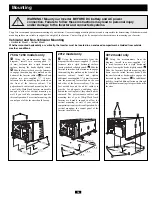
WARNING! Mount your Inverter BEFORE DC battery and AC power
connection. Failure to follow these instructions may lead to personal injury
and/or damage to the Inverter and connected systems.
Tripp Lite recommends permanent mounting of your Inverter. User must supply mounting hardware and is responsible for determining if the hardware and
mounting surface are suitable to support the weight of the Inverter. Contact Tripp Lite if you require further assistance in mounting your Inverter.
Vehicular and Non-Vehicular Mounting
• Horizontal Mount • Vertical Mount
Whether mounted horizontally or vertically, the Inverter must be located in an enclosed compartment, shielded from outside
weather conditions.
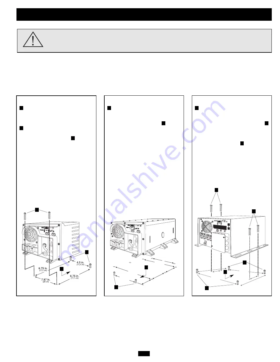
2012 model only
Using the measurements from the
diagram, install two user-supplied ¼" (6 mm)
fasteners into a rigid horizontal surface,
leaving the heads slightly raised.
Slide the
Inverter forward over the fasteners to engage
the mounting feet molded on the front of the
Inverter cabinet. Install and tighten
additional user-supplied ¼" (6 mm) fasteners
into the mounting feet molded on the rear
and sides of the Inverter cabinet. The rear
feet extend beyond the unit’s cabinet to
provide for adequate ventilation space
behind the cooling fan(s); they should not be
removed. The polycarbonate cabinet and
mounting feet of your Utility/Work Truck
Inverter are durable enough to allow for
vertical mounting as well, if your vehicle
compartment requires this configuration. For
vertical mounting, the control panel of the
Inverter should face up.
B
A
750 & 1250 models only
Using the measurements from the
diagram, install two user-supplied ¼"
(6 mm) fasteners into a rigid horizontal
surface, leaving the heads slightly raised.
Slide the Inverter back over the fasteners
to engage the mounting slots molded on the
bottom of the Inverter cabinet.
Install and
tighten two user-supplied ¼" (6 mm)
fasteners into the mounting feet molded on
the front of the Inverter cabinet. The
polycarbonate cabinet and mounting feet of
your Utility/Work Truck Inverter are durable
enough to allow for vertical mounting as
well, if your vehicle compartment requires
this configuration. For vertical mounting, the
control panel of the Inverter should face up.
C
B
A
5.87 in.
(14.91 cm.)
1.64 in.
(4.15 cm.)
5.87 in.
(14.91 cm.)
5.57 in.
(14.16 cm.)
5.57 in.
(14.16 cm.)
9.59 in.
(24.35 cm.)
9.59 in.
(24.35 cm.)
12 in.
30.48 cm.
12 in.
30.48 cm.
4 in.
10.16 cm.
4 in.
10.16 cm.
10.375 in.
26.35 cm.
10.375 in.
26.35 cm.
3012 model only
Using the measurements from the
diagram, install four user-supplied 1/4"
(6 mm) fasteners into a rigid horizontal
surface, leaving the heads slightly raised.
Slide the Inverter's keyhole mounting slots
down over the raised fastener heads. Slide
Inverter forward or backward to engage the
slots and tighten fasteners.
For additional
stability, install additional fasteners through
the additional mounting slots provided on the
Inverter.
C
B
A
A
B
A
B
A
B
C
C
A
C
Summary of Contents for APS 2012 INT
Page 11: ...11R...


