background image

15

5


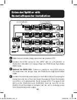
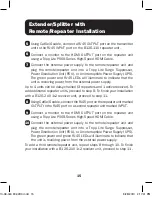
Using Cat5e/6 cable, connect a RJ45 

OUTPUT

 port on the transmitter 

unit to the RJ45 

INPUT

 port on the B126-110 repeater unit.

6


Connect  a  monitor  to  the  HDMI 

OUTPUT

 port on the repeater unit 

using a Tripp Lite P568-Series High-Speed HDMI Cable.

7


Connect the external power supply to the remote/repeater unit and 

plug  the  remote/repeater  unit  into  a  Tripp  Lite  Surge  Suppressor, 
Power Distribution Unit (PDU), or Uninterruptible Power Supply (UPS). 

The green power and RJ45 LEDs will illuminate to indicate that the 
unit is receiving power from the external power supply.

Up to 4 units can be daisy-chained (3 repeaters and 1 active receiver). To 

add additional repeater units, proceed to step 8. To finish your installation 
with a B126-2A0 1x2 receiver unit, proceed to step 11.

8


Using Cat5e/6 cable, connect the RJ45 port on the repeater unit marked 

OUTPUT

 to the RJ45 port on a second repeater unit marked 

INPUT

.

9


Connect  a  monitor  to  the  HDMI 

OUTPUT

 port on the repeater unit 

using a Tripp Lite P568-Series High-Speed HDMI Cable.

10


Connect the external power supply to the remote/repeater unit and 
plug  the  remote/repeater  unit  into  a  Tripp  Lite  Surge  Suppressor, 

Power Distribution Unit (PDU), or Uninterruptible Power Supply (UPS). 
The green power and green RJ45 LEDs will illuminate to indicate that 
the unit is receiving power from the external power supply.

To add a third remote/repeater unit, repeat steps 8 through 10. To finish 

your installation with a B126-2A0 1x2 receiver unit, proceed to step 11.

Extender/Splitter with 

Remote/Repeater Installation

13-08-043 93-32D0.indd   15

8/28/2013   2:17:41 PM

Summary of Contents for B126-2A0

Page 1: ...c h a n c e t o w i n a F R E E T r i p p L i t e p r o d u c t w w w t r i p p l i t e c o m w a r r a n t y Package Contents 2 Product Features 2 Mounting Instructions 4 Standard 1 x 2 Extender Kit...

Page 2: ...um distance and resolution Further expand the range and number of monitors by adding B126 110 repeater units Add up to three repeaters on each Cat5e 6 channel for a total of 4 displays per channel An...

Page 3: ...annel or PCM HDCP and 3D compatible Plug and play No software or drivers required Compatible with all operating systems Mounting hardware included Optional Accessories B126 110 Remote Repeater Unit N2...

Page 4: ...es show the different ways the included mounting brackets can be attached for different mounting methods Note The images below show a B126 1A1 HDMI over Cat5 Receiver Unit but the mounting hardware in...

Page 5: ...such as Tripp Lite s N202 Series is required to achieve maximum distance and resolution 3 The diagram below shows the maximum extension distance when using Cat6 cabling When using Cat5 cabling the max...

Page 6: ...the external power supply to the receiver unit and plug the receiver unit into a Tripp Lite Surge Suppressor Power Distribution Unit PDU or Uninterruptible Power Supply UPS The green RJ45 LED illumina...

Page 7: ...am below shows the maximum extension distance when using either Cat5e or Cat6 cabling 24 AWG solid wire Cat5e 6 cable such as Tripp Lite s N202 Series is required to achieve maximum distance and resol...

Page 8: ...RJ45 LEDs will illuminate to indicate that the unit is receiving power from the external power supply Up to 4 units can be daisy chained 3 repeaters and 1 active receiver To add additional repeater u...

Page 9: ...rge Suppressor Power Distribution Unit PDU or Uninterruptible Power Supply UPS The green RJ45 LED illuminates to indicate that it is receiving power from the external power supply 15 Turn on the power...

Page 10: ...e set to transmit a stereo audio signal by default Press the Audio button on the transmitter unit to switch to 7 1 channel surround sound audio 7 1 channel surround sound signal will be Multi Channel...

Page 11: ...ed HDMI Cable 3 Optional for B126 004 Connect a monitor to the LOCAL port on the transmitter unit using a Tripp Lite P568 Series High Speed HDMI Cable 4 Connect the external power supply to the transm...

Page 12: ...8 for the OUTPUT 2 port on the receiver unit 10 Turn on the power to the connected devices The orange RJ45 LEDs on the transmitter and receiver units will illuminate to indicate that a signal is being...

Page 13: ...signal by default Press the Audio button on the transmitter unit to switch to 7 1 channel surround sound audio 7 1 channel surround sound signal will be Multi Channel or PCM 4 The diagram below shows...

Page 14: ...1 x 2 EXTENDER REMOTE UNIT MODEL B126 2A0 HDMI OVER Cat5 1 x 2 EXTENDER REMOTE UNIT MODEL B126 2A0 14 1 Make sure all devices being connected are powered OFF 2 Connect the HDMI source to the INPUT por...

Page 15: ...h your installation with a B126 2A0 1x2 receiver unit proceed to step 11 8 Using Cat5e 6 cable connect the RJ45 port on the repeater unit marked OUTPUT to the RJ45 port on a second repeater unit marke...

Page 16: ...indicate that it is receiving power from the external power supply 15 Repeat steps 5 through 14 for each additional RJ45 OUTPUT port on the transmitter unit 16 Turn on the power to the connected devi...

Page 17: ...lity Use the mini screwdriver included with the product to adjust this setting until an acceptable image is displayed Note An improper Equalization setting can cause the monitor not to display an imag...

Page 18: ...ect it between a computer and a network to verify that it establishes a network connection 7 Do you have any patch panels or other devices in between the transmitter repeater and receiver units Tripp...

Page 19: ...e aforesaid limitation s or exclusion s may not apply to the purchaser EXCEPT AS PROVIDED ABOVE IN NO EVENT WILL TRIPP LITE BE LIABLE FOR DIRECT INDIRECT SPECIAL INCIDENTAL OR CONSEQUENTIAL DAMAGES AR...

Page 20: ...harmful interference to radio or television reception which can be determined by turning the equipment off and on the user is encouraged to try to correct the interference by one or more of the follow...

Reviews: