background image

4

I

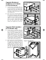
Suggested Rackmount
Installation for 2U Models
in 4-Post Enclosures

1)

Measure the depth of your rack from the
outside surface of the front mounting rail
to the outside surface of the rear mounting
rail.

2)

Connect the rear mounting ears (A) to the
mounting extensions (B) using four wing
bolts and flat washers (C) and locking nuts
(D) each. The wing bolts should be left
only finger-tight so that they may be ad-
justed later.

3)

On both sides of your Battery Pack, con-
nect both front mounting ears (E) with four
screws and flat washers each (F) so their
mounting surfaces are  even with the front
of your Battery Pack's metal case. Connect
the mounting extensions (G) to the Battery
Pack using four screws and flat washers
(H) each. Adjust the rear mounting ears on
the mounting extensions so that the dis-
tance from the front mounting ears to rear
mounting ears matches the depth of your
rack.

4)

Have one or more assistants lift the Battery
Pack and hold it in position until this step
is complete. Insert the Battery Pack into its
intended rack space, pressing its rear mount-
ing ears (I) inward so that they fit past the
rack's front (J) and rear (K) mounting rails,
until the mounting surfaces of the front
ears (L) meet the outside of the rack's front
rails. Adjust the rear mounting ear until the
mounting surface of the rear ears meet the
outside of the rear rails, then tighten the
wing bolts holding the mounting ears to
the mounting extensions. Connect the front
mounting ears of the Battery Pack to the
rack's front mounting rails with two screws
and flat washers (M, user supplied: match
to the rails' threads) on each side. Connect
the rear mounting ears to the rear mount-
ing rails of the rack with two screws and
flat washers (N, user supplied: match to
the rails' threads) on each side.

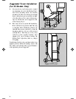
Figure 3

(2U 4-Post)

Figure 1 (2U 4-Post)

Figure 2
(2U 4-Post)

Summary of Contents for BP12V81

Page 1: ...attery power due to the possibility of dangerous arcing There are no user serviceable parts inside the Battery Pack Do not open the Battery Pack for any reason Do not attempt to replace the internal b...

Page 2: ...y youmust determine the fitness of your mounting hardware before attempting to mount the Battery Pack Suggested Rackmount Installation for 3U Models in 4 Post Enclosures 1 Loosen the wingnuts A on eac...

Page 3: ...hers provided F Do not attach the mounting ears to the Battery Pack s front mounting holes 3 Have one or more assistants lift the Battery Pack and hold it in position until this step is complete Inser...

Page 4: ...ont mounting ears to rear mounting ears matches the depth of your rack 4 Have one or more assistants lift the Battery Pack and hold it in position until this step is complete Insert the Battery Pack i...

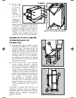
Page 5: ...E on each side Suggested Wall Installation for 2U Models Only 1 On both sides of your Battery Pack con nect one mounting ear A to the Battery Pack s four front mounting holes and another mounting ear...

Page 6: ...ssistants lift the Battery Pack and hold it in position until this step is complete Move the Battery Pack to its intended floor space and hold it so that the mounting surfaces of its ears D are level...

Page 7: ...uire longer recharge times If your battery pack does not feature an external battery connector B you use a Power Cable Y Adapter sold separately by Tripp Lite to con nect two of them to a single UPS C...

Page 8: ...shipping or delivery charges prepaid to Tripp Lite 1111 W 35th Street Chicago IL 60609 Seller will pay return shipping charges Call Tripp Lite at 773 869 1234 before sending any equipment back for re...

Page 9: ...or medio de la bater a pues existe la posibilidad de crear un arco de voltaje peligroso Este paquete de bater as no contiene partes interiores que puedan ser reparadas por el usuario Por ning n motivo...

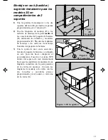
Page 10: ...nte sedebedeterminarelequipoapropiadoantesderealizarelmontajedelpaquetedebater as Figura 1 3U 4 soportes Figura 2 3U 4 soportes Figura 3 3U 4 soportes Montaje en rack bastidor sugerido Instalaci n par...

Page 11: ...er as E utilizando los tornillos y arandelas proporcionados F No una las leng etas de montaje a los orificios de montaje frontales del paquete de bater as 3 Con la ayuda de uno o m s asistentes levant...

Page 12: ...ro tornillos y arandelas planas para cada una H Ajuste las leng etas de montaje posteriores sobre las extensiones de montaje de modo que la distancia desde las leng etas de montaje frontales hasta las...

Page 13: ...e montaje de la leng eta debe dirigirse al frente del paquete de bater as 2 Con la ayuda de uno o m s asistentes levante el paquete de bater as y sost ngalo en esta posici n hasta completar el procedi...

Page 14: ...o Una las leng etas al suelo mediante dos tornillos y arandelas planas proporcionados por el usuario E para cada una Si no se colocan los pernos al paquete de bater as para fijarlo en su sitio existir...

Page 15: ...para bater as externas B se puede utilizar un adaptador en Y para el cable de corriente que Tripp Lite vende por separado para conectar dos de ellos a un solo sistema UPS Conexi ndepaquetesdebater as...

Page 16: ...aque y traslado pagados previamente a Tripp Lite 1111 W 35th Street Chicago IL 60609 El distribuidor pagar los gastos de devoluci n Llame a Tripp Lite al tel fono 773 869 1234 antes de devolver cualqu...

Page 17: ...rcs lectriquesdangereux Iln yapasdepi ces l int rieurdubloc batteriequel utilisateurpuisser parerparlui m me Ne l ouvrez pas quelqu en soit la raison N essayezpasderemplacerlesbatteriesinternes Cesbat...

Page 18: ...evez d terminer l adaptation de vos pi ces de montageavantdetenterd installervotrebloc batterie Figure 1 3U 4 piliers Figure 2 3U 4 piliers Figure 3 3U 4 piliers B ti sugg r Installation des mod les 3...

Page 19: ...bloc batterie E en utilisant les vis et les rondelles fournies F Ne fixez pas les oreilles de montage aux trous avant du bloc batterie 3 Ayez un ou plusieurs assistants pour soulever le bloc batterie...

Page 20: ...ri re soitlam mequelaprofondeurdevotreb ti 4 Ayezunouplusieursassistantspoursoulever le bloc batterie et le maintenir en position jusqu ce que cette tape soit accomplie Ins rez le bloc batterie dans s...

Page 21: ...ion murale sugg r e pour les mod les 2U seulement 1 Reliez une oreille de montage de chaque c t du bloc batterie A ses quatre trous de montage avant et une autre oreille de mon tage B au quatre trous...

Page 22: ...bloc batterie et le maintenir en position jusqu ce que cette tape soit accomplie D placez le bloc batterie vers son espace pr vu au sol et maintenez le de fa on ce que les surfaces de montage de ses o...

Page 23: ...Si votre bloc batterie n est pas dot d un connecteur de batterie externe B vous pouvez utiliser un raccord de c ble en Y vendu s par ment par Tripp Lite pour relier deux blocs un seul syst me UPS Con...

Page 24: ...livraison Tripp Lite 1111 W 35th Street Chicago IL 60609 Le vendeur paiera les frais d exp dition au retour Appelez Tripp Lite 773 869 1234 avant d envoyer du mat riel r parer Les consommateurs du Me...

Page 25: ...d auf Grund von Elektroden berschlagsgefahr DasBatteriesystementh ltkeinevomBenutzerzuwartendenTeile Ein ffnendesBatteriesystems sollteinjedemFallunterlassenwerden VersuchenSienicht dieinternenBatteri...

Page 26: ...und die Seitenst tzen schrauben Abbildung 2 3U 4 Pfosten Abbildung 1 3U 4 Pfosten Abbildung 3 3U 4 Pfosten FARBAUSWAHL Nur bestimmte Modelle Einige Batteriesysteme sind mit zwei verschiedenfarbigen Au...

Page 27: ...festigungsl chern des Batteriesystems E mit Hilfe der beiliegenden Schrauben und Unterlegscheiben F Achten Sie dabei darauf die Haltevorrichtungen nicht in den vorderen Befestigungsl chern des Batteri...

Page 28: ...legscheiben H Justieren Sie die hinteren Halte vorrichtungen mit den Halte verl ngerungen so dass der Abstand von den vorderen zu den hinteren Halte vorrichtungen mit der Tiefe Ihres Gestells bereinst...

Page 29: ...rseite des Batteriesystems ausgerichtet sein 2 Heben Sie das Batteriesystem mit einem oder mehreren Assistenten an und halten Sie es in Position bis dieser Schritt vollst ndig ausgef hrt ist F hren Si...

Page 30: ...rn mit jeweils vier Schrauben und Unterlegscheiben Die Enden der Haltevorrichtungen sollten auf den entgegengesetzten Seiten des Batteriesystems herausragen 2 Heben Sie das Batteriesystem mit einem od...

Page 31: ...n Tripp Lite einen Y Adapter separat bestellen um zwei Batterien an ein USV Ger t anzuschlie en Anschlie en von Batteriesystemen mit abnehmbaren Leitungskabeln So schlie en Sie eine einzelne Batterie...

Page 32: ...ch vor dem Versand von Ger ten zu Reparaturzwecken mit Tripp Lite telefonisch unter 1 773 869 1234 in Verbindung Kunden in Mexiko erhalten Kundendienstleistungen gem dieser Garantiebestimmungen durch...

Reviews: