background image

2

NOTE: 

Read the entire instruction manual before you start installation and assembly.

Warranty & Warranty Registration

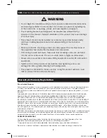
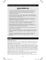
WARNING

•  Do not begin the installation until you have read and understood the instructions 

and warnings contained in this manual. If you have any questions regarding any 
of the instructions or warnings, please visit www.tripplite.com/support.

•  This mounting bracket was designed to be installed and utilized ONLY as 

 specified in this manual. Improper installation of this product may cause damage 
or serious injury.

•  This product should only be installed by someone of good mechanical  ability, 

with basic building experience and a full understanding of this instruction 
manual.

•  Make sure that the mounting surface can safely support the combined load of 

the equipment and all attached hardware and components.

•  If mounting to wood wall studs, make sure that mounting screws are anchored 

into the center of the studs. The use of a stud finder is highly recommended.

•  Always use an assistant or mechanical lifting equipment to safely lift and position 

equipment.

•  Tighten screws firmly, but do not over-tighten. Over-tightening screws can 

damage the items, greatly reducing their holding power.

•  This product is intended for indoor use only. Using this product outdoors could 

lead to product failure and personal injury.

5-Year Limited Warranty

Seller warrants this product, if used in accordance with all applicable instructions, to be free from original defects 

in material and workmanship for a period of 5 years from the date of initial purchase. If the product should 
prove defective in material or workmanship within that period, Seller will repair or replace the product, in its sole 

discretion.
THIS WARRANTY DOES NOT APPLY TO NORMAL WEAR OR TO DAMAGE RESULTING FROM ACCIDENT, MISUSE, 
ABUSE OR NEGLECT. SELLER MAKES NO EXPRESS WARRANTIES OTHER THAN THE WARRANTY EXPRESSLY 

SET FORTH HEREIN. EXCEPT TO THE EXTENT PROHIBITED BY APPLICABLE LAW, ALL IMPLIED WARRANTIES, 
INCLUDING ALL WARRANTIES OF MERCHANTABILITY OR FITNESS, ARE LIMITED IN DURATION TO THE WARRANTY 

PERIOD SET FORTH ABOVE; AND THIS WARRANTY EXPRESSLY EXCLUDES ALL INCIDENTAL AND CONSEQUENTIAL 
DAMAGES. (Some states do not allow limitations on how long an implied warranty lasts, and some states do not 
allow the exclusion or limitation of incidental or consequential damages, so the above limitations or exclusions 

may not apply to you. This warranty gives you specific legal rights, and you may have other rights which vary from 
jurisdiction to jurisdiction).

WARNING: The individual user should take care to determine prior to use whether this device is suitable, adequate 

or safe for the use intended. Since individual applications are subject to great variation, the manufacturer makes 

no representation or warranty as to the suitability or fitness of these devices for any specific application.

WARRANTY REGISTRATION

Visit www.tripplite.com/warranty today to register the warranty for your new Tripp Lite product. You’ll be 

automatically entered into a drawing for a chance to win a FREE Tripp Lite product!*
* No purchase necessary. Void where prohibited. Some restrictions apply. See website for details.
Tripp Lite has a policy of continuous improvement. Specifications are subject to change without notice.

14-03-249-93332F.indb   2

4/14/2014   10:48:28 AM

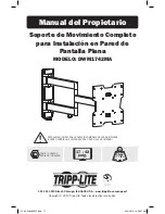
Summary of Contents for DWM1742MA

Page 1: ...EED MAXIMUM LISTED WEIGHT CAPACITY SERIOUS INJURY OR PROPERTY DAMAGE MAY OCCUR 1111 W 35th Street Chicago IL 60609 USA www tripplite com support Copyright 2014 Tripp Lite All rights reserved 75x75 100x100 200x100 200x200 42 MAX 35kg 77lbs MAX 14 03 249 93332F indb 1 4 14 2014 10 48 28 AM ...

Page 2: ...the product should prove defective in material or workmanship within that period Seller will repair or replace the product in its sole discretion THIS WARRANTY DOES NOT APPLY TO NORMAL WEAR OR TO DAMAGE RESULTING FROM ACCIDENT MISUSE ABUSE OR NEGLECT SELLER MAKES NO EXPRESS WARRANTIES OTHER THAN THE WARRANTY EXPRESSLY SET FORTH HEREIN EXCEPT TO THE EXTENT PROHIBITED BY APPLICABLE LAW ALL IMPLIED W...

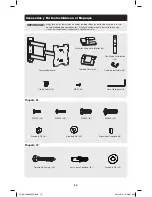
Page 3: ...lty visit www tripplite com support for service Arm Assembly Mounting Template x1 Cable Cover x1 Middle Cover x1 Top and Bottom Covers x2 Cable Clip x1 M4X5 x1 Hex Key x1 D5 Washer x4 M4X14 x4 Anchor Bolt x4 Concrete Anchor x4 D6 Washer x4 D8 Washer x4 M5X14 x4 Small Spacer x8 M6X14 x4 M8X20 x4 Package M Package W 14 03 249 93332F indb 3 4 14 2014 10 48 28 AM ...

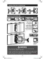
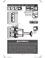
Page 4: ...nder is highly recommended Installers are responsible to provide hardware for other types of mounting situations Installers must verify that the supporting surface will safely support the combined load of the equipment and all attached hardware and components 1 2 Anchor Bolt D6 Washer loosen remove Position the Mounting Template to location with the UP pointing towards the ceiling Mark the exact l...

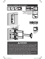
Page 5: ...25mm 1 toward the middle of the block from either end An electric drill on a slow setting is suggested to drill the hole rather than a hammer drill so as to avoid breaking out the back of the hole when entering a hollow section Installers must verify that the supporting surface will safely support the combined load of the equipment and all attached hardware and components Screw the wall mount onto...

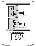
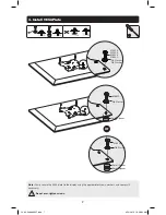
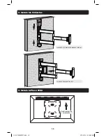
Page 6: ...6 3 Install Covers 4 Install VESA Plate Insert the Top and Bottom Covers Install the Middle Cover Top of Display 14 03 249 93332F indb 6 4 14 2014 10 48 32 AM ...

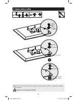
Page 7: ... display using the appropriate screws washers and spacers if necessary Do not over tighten screws or M4X14 M5X14 M6X14 M8X20 M8X20 M8X20 D5 Washer D8 Washer D8 Washer D8 Washer Small Spacer Small Spacer Small Spacer TV 14 03 249 93332F indb 7 4 14 2014 10 48 32 AM ...

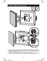
Page 8: ... thumbscrew over the top flange of wall plate arm Make sure the VESA plate s lower screw fits inside of the wall plate arm s lower hole Position a level on the horizontal and vertical sides of the display and adjust as needed Reattach the lower thumbscrew to the VESA mount removed in step 1 Tighten both thumbscrews 14 03 249 93332F indb 8 4 14 2014 10 48 33 AM ...

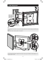
Page 9: ...splay installed Connect cables to your display and route cables through cable clip then attach the cable cover to hold the cable in place Note Leave slack in cable for cantilever arm movement Attach Cable Clip to the wall mount arm using the provided M4X5 screw Cable Cover Cable Clip M4X5 Hex Key 14 03 249 93332F indb 9 4 14 2014 10 48 35 AM ...

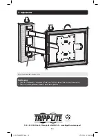
Page 10: ...he bracket is secure and safe to use at regular intervals at least every three months Please visit www tripplite com support if you have any questions 180 180 15 15 3 3 1111 W 35th Street Chicago IL 60609 USA www tripplite com support 14 03 249 93332F indb 10 4 14 2014 10 48 36 AM ...

Page 11: ...EXCEDA LA CAPACIDAD MÁXIMA DE CARGA INDICADA PUEDE OCURRIR UNA LESIÓN SEVERA O DAÑO A LA PROPIEDAD 1111 W 35th Street Chicago IL 60609 USA www tripplite com support Copyright 2014 Tripp Lite Todos los derechos reservados 75x75 100x100 200x100 200x200 35 kg 77 lbs MÁX MÁS D E 17 42 pulg 14 03 249 93332F indb 11 4 14 2014 10 48 37 AM ...

Page 12: ... Limitada por 5 Años El vendedor garantiza este producto si se usa de acuerdo con todas las instrucciones aplicables de que está libre de defectos en material y mano de obra por un período de 5 años a partir de la fecha de compra inicial Si el producto prueba ser defectuoso en material o mano de obra dentro de ese período el vendedor reparará o reemplazará el producto a su entera discreción ESTA G...

Page 13: ...ww tripplite com support para solicitar servicio Conjunto de Brazo Plantilla de Instalación x1 Cubierta del Cable x1 Cubierta Central x1 Cubiertas Superior e Inferior x2 Clip de Cable x1 M4X5 x1 Llave Hexagonal x1 Arandela D5 x4 M4X14 x4 Tornillo de Anclaje x4 Ancla para Concreto x4 Arandela D6 x4 Arandela D8 x4 M5X14 x4 Espaciador Pequeño x8 M6X14 x4 M8X20 x4 Paquete M Paquete W 14 03 249 93332F ...

Page 14: ...te de pared a la pared Barrene los orificios piloto ADVERTENCIA Cerciórese que los tornillos de instalación estén anclados en el centro de los montantes Es muy recomendable usar un detector de montantes Los instaladores son responsables de proporcionar los accesorios para otros tipos de soluciones de instalación Los instaladores deben verificar que la superficie de apoyo soporte con seguridad la c...

Page 15: ...ente a 25 mm 1 hacia el centro del bloque en cada extremo Se sugiere utilizar un taladro eléctrico a baja velocidad para barrenar el orificio en vez de un rotomartillo para evitar rotura de la parte posterior del orificio al entrar en una sección hueca Los instaladores deben verificar que la superficie de apoyo soporte con seguridad la carga combinada del equipo y los accesorios y componentes agre...

Page 16: ...16 3 Instale las Cubiertas 4 Instale la Placa VESA Inserte las Cubiertas Superior e Inferior Instale la Cubierta Central Parte superior de la Pantalla 14 03 249 93332F indb 16 4 14 2014 10 48 39 AM ...

Page 17: ...ornillos arandelas y espaciadores apropiados si fuera necesario No apriete excesivamente los tornillos o M4X14 M5X14 M6X14 M8X20 M8X20 M8X20 Arandela D5 Arandela D8 Arandela D8 Arandela D8 Espaciador Pequeño Espaciador Pequeño Espaciador Pequeño 14 03 249 93332F indb 17 4 14 2014 10 48 39 AM ...

Page 18: ...a del brazo de la placa de pared Cerciórese de que los tornillos inferiores de la placa VESA ajusten dentro del orificio inferior del brazo de la placa de pared Coloque un nivel en los lados horizontal y vertical de la pantalla y ajuste según sea necesario Reinstale el tornillo de mariposa inferior al soporte VESA retirado en el paso 1 Apriete ambos tornillos de mariposa 14 03 249 93332F indb 18 4...

Page 19: ...pantalla y conduzca los cables a través del clip del cable después coloque la cubierta del cable para sujetar el cable en su sitio Nota Deje una holgura en el cable para el movimiento del brazo en cantilever Instale el clip del cable al brazo del soporte de pared usando el tornillo M4X5 suministrado Cubierta del Cable Clip de Cable M4X5 Llave Hexagonal 14 03 249 93332F indb 19 4 14 2014 10 48 40 A...

Page 20: ...valos regulares al menos cada tres meses que el soporte esté seguro para usarse Si tiene alguna pregunta visite por favor a www tripplite com support 180 180 15 15 3 3 1111 W 35th Street Chicago IL 60609 USA www tripplite com support MÁS D E 14 03 249 93332F indb 20 4 14 2014 10 48 41 AM ...

Page 21: ...PONDÉRALE MAXIMUM INDIQUÉE DES BLESSURES GRAVES OU DES DOMMAGES MATÉRIELS RISQUENT DE SE PRODUIRE 1111 W 35th Street Chicago IL USA 60609 www tripplite com support Droits d auteur 2014 Tripp Lite Tous droits réservés 75x75 100x100 200x100 200x200 35 kg 77 lbs MAX utsch 41 17 42 po 43 107 cm 14 03 249 93332F indb 21 4 14 2014 10 48 41 AM ...

Page 22: ...uit s il est utilisé conformément à toutes les instructions applicables est exempt de tous défauts de matériaux et de fabrication pour une période de 5 ans à partir de la date d achat initiale Si le produit s avère défectueux en raison d un vice de matière ou de fabrication au cours de cette période le vendeur s engage à réparer ou remplacer le produit à sa seule discrétion CETTE GARANTIE NE S APP...

Page 23: ...fectueuses visitez www tripplite com support pour obtenir de l aide Ensemble du bras Modèle de montage x1 Couvre câble x1 Couvercle du milieu x1 Couvercles supérieur et inférieur x2 Serre câble x1 M4X5 x1 Clé hexagonale x1 Rondelle D5 x4 M4X14 x4 Anchor Bolt x4 Ancrage à béton x4 Rondelle D6 x4 Rondelle D8 x4 M5X14 x4 Petite entretoise x8 M6X14 x4 M8X20 x4 Emballage M Emballage W 14 03 249 93332F ...

Page 24: ...nt trous AVERTISSEMENT S assurer que les vis de montage sont ancrées au centre des montants Il est fortement recommandé d utiliser un localisateur de montants Les installateurs sont responsables de fournir la quincaillerie pour tout autre type de situations de montage Les installateurs doivent s assurer que la surface d appui va supporter sans risque la charge combinée de l équipement et de tout l...

Page 25: ...ctions solides se trouvent habituellement à 25 mm 1 po vers le milieu du bloc à partir de chaque extrémité Il est suggéré d utiliser une perceuse électrique pour percer un trou plutôt qu un marteau perforateur afin d éviter d endommager l arrière du trou en présence d un espace vide Les installateurs doivent s assurer que la surface d appui va supporter sans risque la charge combinée de l équipeme...

Page 26: ...26 3 Installer les couvercles 4 Installer la plaque VESA Insérer les couvercles supérieur et inférieur Installer le couvercle du milieu Dessus de l écran 14 03 249 93332F indb 26 4 14 2014 10 48 43 AM ...

Page 27: ...an en utilisant les vis les rondelles et les entretoises au besoin Ne pas trop serrer les vis ou M4X14 M5X14 M6X14 M8X20 M8X20 M8X20 Rondelle D5 Rondelle D8 Rondelle D8 Rondelle D8 Petite entretoise Petite entretoise Petite entretoise 14 03 249 93332F indb 27 4 14 2014 10 48 43 AM ...

Page 28: ...VESA sur la bride supérieure du bras de la plaque murale S assurer que la vis inférieure de la plaque VESA s insère dans le trou inférieur du bras de la plaque murale Positionner un niveau sur les côtés horizontaux et verticaux de l écran et ajuster au besoin Rattacher la vis de serrage inférieure au montage VESA enlevée à l étape 1 Serrer les deux vis de serrage 14 03 249 93332F indb 28 4 14 2014...

Page 29: ... câbles à l écran et acheminer les câbles à travers le serre câble puis attacher le couvre câble pour retenir le câble en place Remarque Laisser suffisamment de mou dans le câble pour permettre le mouvement du bras en surplomb Attacher le serre câble au bras de montage mural en utilisant la vis M4X5 fournie Couvre câble Serre câble M4X5 Clé hexagonale 14 03 249 93332F indb 29 4 14 2014 10 48 44 AM...

Page 30: ...s réguliers que le support peut être utilisé de façon sûre et sécuritaire au moins tous les trois mois Veuillez visiter www tripplite com support si vous avez des questions 180 180 15 15 3 3 1111 W 35th Street Chicago IL USA 60609 www tripplite com support 14 03 249 93332F indb 30 4 14 2014 10 48 45 AM ...

Page 31: ...АЙТЕ МАКСИМАЛЬНО ДОПУСТИМЫЙ ВЕС ЭТО МОЖЕТ ПРИЧИНИТЬ СУЩЕСТВЕННЫЙ ВРЕД ЗДОРОВЬЮ ЛЮДЕЙ ИЛИ МАТЕРИАЛЬНЫЙ УЩЕРБ 1111W 35th Street Chicago IL 60609 USA www tripplite com support Охраняется авторским правом 2014Tripp Lite Перепечатка запрещается 75x75 100x100 200x100 200x200 35 кг МАКС 17 42 дюймов 43 107 cm 14 03 249 93332F indb 31 4 14 2014 10 48 45 AM ...

Page 32: ...ет отсутствие изначальных дефектов материала или изготовления в течение 5 лет с момента первой покупки данного изделия при условии его использования в соответствии со всеми применимыми к нему указаниями В случае проявления каких либо дефектов материала или изготовления в течение указанного периода Продавец осуществляет ремонт или замену данного изделия исключительно по своему усмотрению ДЕЙСТВИЕ Н...

Page 33: ...lite com support Кронштейн в сборе Монтажный шаблон 1 шт Крышка кабельного отсека 1 шт Средняя заглушка 1 шт Верхняя и нижняя заглушки 2 шт Кабельный хомут 1 шт M4X5 1 шт Шестигранный ключ 1 шт Шайба D5 4 шт M4X14 4 шт Анкерный болт 4 шт Анкер для бетона 4 шт Шайба D6 4 шт Шайба D8 4 шт M5X14 4 шт Малая проставка 8 шт M6X14 4 шт M8X20 4 шт Упаковочный комплект M Упаковочный комплектW 14 03 249 933...

Page 34: ...лите направляющие отверстия ВНИМАНИЕ Необходимо обеспечить ввертывание крепежных винтов по центру элементов каркаса С этой целью настоятельно рекомендуется использование детектора неоднородностей Ответственность за обеспечение подходящей крепежной оснастки для других способов монтажа возлагается на установщика Установщик обязан убедиться в том что опорная поверхность с запасом выдержит суммарную н...

Page 35: ... расстоянии 25 мм от любого из краев блока к его центру Во избежание разрушения задней стенки отверстия при попадании сверла в полую часть для высверливания отверстия рекомендуется использовать электрическую дрель на малой скорости вращения вместо перфоратора Установщик обязан убедиться в том что опорная поверхность с запасом выдержит суммарную нагрузку создаваемую оборудованием и всеми входящими ...

Page 36: ...36 3 Установка заглушек 4 Установите на место пластинуVESA Вставьте верхнюю и нижнюю заглушки Установите среднюю заглушку Верх дисплея 14 03 249 93332F indb 36 4 14 2014 10 48 47 AM ...

Page 37: ...A к дисплею с использованием соответствующих винтов шайб и распорок при необходимости Не перетягивайте винты либо M4X14 M5X14 M6X14 M8X20 M8X20 M8X20 Шайба D5 Шайба D8 Шайба D8 Шайба D8 Малая проставка Малая проставка Малая проставка 14 03 249 93332F indb 37 4 14 2014 10 48 47 AM ...

Page 38: ...рхний фланец кронштейна пластины для настенного монтажа Убедитесь в том что нижний винт для крепления пластиныVESA свободно входит в нижнее отверстие пластины для настенного монтажа Приложите уровень к горизонтальным и вертикальным сторонам дисплея и скорректируйте его положение в случае необходимости Вверните нижний винт с накатанной головкой вывернутый на шаге 1 обратно в кронштейнVESA Затяните ...

Page 39: ...гранного ключа Подключите кабели к дисплею и проведите кабели через хомут а затем защелкните крышку кабельного отсека для фиксации кабелей Примечание Для перемещения консольного рычага оставляйте кабель ненатянутым Прикрепите кабельный хомут к кронштейну с помощью винта входящего в комплект Крышка кабельного отсека Кабельный хомут M4X5 Шестигранный ключ 14 03 249 93332F indb 39 4 14 2014 10 48 48 ...

Page 40: ... месяца проверяйте надежность крепления кронштейна и безопасность его использования В случае возникновения каких либо вопросов приглашаем вас посетить страницу www tripplite com support 180 180 15 15 3 3 1111W 35th Street Chicago IL 60609 USA www tripplite com support 14 03 249 93332F indb 40 4 14 2014 10 48 48 AM ...

Page 41: ...CHT ÜBERSCHRITTEN WERDEN ES KÖNNEN SCHWERE KÖRPERVERLETZUNGEN ODER ERHEBLICHE SACHSCHÄDEN EINTRETEN 1111 W 35th Street Chicago IL 60609 USA www tripplite com support Copyright 2014 Tripp Lite Alle Rechte vorbehalten 75 x 75 100 x 100 200 x 100 200 x 200 35 kg MAX 17 42 Zoll 43 107 cm 14 03 249 93332F indb 41 4 14 2014 10 48 48 AM ...

Page 42: ...b Kaufdatum dass das Produkt weder Material noch Herstellungsfehler aufweist wenn es gemäß aller zutreffenden Anweisungen verwendet wird Wenn das Produkt in diesem Zeitraum Material oder Herstellungsfehler aufweist kann der Verkäufer diese Fehler nach eigenem Ermessen beheben oder das Produkt ersetzen DIE NORMALE ABNUTZUNG ODER BESCHÄDIGUNGEN AUFGRUND VON UNFÄLLEN MISSBRAUCH ODER UNTERLASSUNG WERD...

Page 43: ...d besuchen Sie www tripplite com support Armmontage Halterungsschablone x1 Kabelabdeckung x1 Mittlere Abdeckung x1 Obere und untere Abdeckungen x2 Kabelschelle x1 M4X5 x1 Inbusschlüssel x1 D5 Beilagscheibe x4 M4X14 x4 Ankerbolzen x4 Betonanker x4 D6 Beilagscheibe x4 D8 Beilagscheibe x4 M5X14 x4 Kleiner Abstandhalter x8 M6X14 x4 M8X20 x4 Paket M Paket W 14 03 249 93332F indb 43 4 14 2014 10 48 49 A...

Page 44: ...and festschrauben Bohren Sie die Führungslöcher WARNUNG Stellen Sie sicher dass die Befestigungsschrauben in der Mitte der Balken verankert sind Wir empfehlen die Verwendung eines Balkensuchers Für andere Befestigungsarten muss das Material vom Monteur bereitgestellt werden Der Monteur muss sicherstellen dass die verwendete Montagefläche das Gesamtgewicht des Geräts sowie das zugehörige Material u...

Page 45: ...er Enden entfernt zur Mitte des Betonsteines hin Anstelle einer Schlagbohrmaschine wird zum Bohren des Bohrloches eine elektrische Bohrmaschine mit geringer Drehzahl empfohlen um ein Ausbrechen des Werkstoffs am Bohrlochausgang zu verhindern wo der Hohlraum beginnt Der Monteur muss sicherstellen dass die verwendete Montagefläche das Gesamtgewicht des Geräts einschließlich des zugehörigen Materials...

Page 46: ...3 Installieren der Abdeckungen 4 Installieren der VESA Platte Die obere und untere Abdeckung einsetzen Die Mittelabdeckung montieren Oberseite des Bildschirms 14 03 249 93332F indb 46 4 14 2014 10 48 50 AM ...

Page 47: ...d Abstandhalter falls erforderlich fest am Bildschirm anschrauben Die Schrauben nicht überdrehen oder M4X14 M5X14 M6X14 M8X20 M8X20 M8X20 D5 Beilagscheibe D8 Beilagscheibe D8 Beilagscheibe D8 Beilagscheibe Kleiner Abstandhalter Kleiner Abstandhalter Kleiner Abstandhalter 14 03 249 93332F indb 47 4 14 2014 10 48 50 AM ...

Page 48: ...plattenarms einsetzen Vergewissern Sie sich dass die untere Schraube der VESA Platte ins Innere der unteren Öffnung am Wandplattenarm passt An die horizontalen und vertikalen Kanten des Bildschirms eine Wasserwaage anlegen und die Bildschirmstellung je nach Bedarf justieren Die untere Fingerschraube wieder an die VESA Platte anschrauben diese wurde im Schritt 1 entfernt Beide Fingerschrauben fest ...

Page 49: ...e die Kabel am Bildschirm ein und ziehen Sie sie durch die Kabelschelle Bringen Sie anschließend die Kabelabdeckung an um das Kabel zu arretieren Hinweis Lassen Sie das Kabel locker damit sich der freitragende Arm bewegen kann Die Kabelklemme unter Verwendung der mitgelieferten Schraube M4x5 am Wandhalterungsarm befestigen Kabelabdeckung Kabelschelle M4X5 Inbusschlüssel 14 03 249 93332F indb 49 4 ...

Page 50: ...ng an Wartung Stellen Sie in regelmäßigen Abständen mindestens alle drei Monate sicher dass die Klammer sicher angebracht ist Falls Sie Fragen haben besuchen Sie www tripplite com support 180 180 15 15 3 3 14 03 249 93332F indb 50 4 14 2014 10 48 51 AM ...

Page 51: ...51 14 03 249 93332F indb 51 4 14 2014 10 48 51 AM ...

Page 52: ...52 1111 W 35th Street Chicago IL 60609 USA www tripplite com support 14 03 249 93 332F_revA 14 03 249 93332F indb 52 4 14 2014 10 48 51 AM ...

Reviews: