213
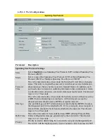
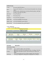
Hello Time
This is the time interval (in seconds) at which the root switch transmits a
configuration message. The root bridge determines Hello Time, Max Age
and Forwarding Delay.
Forward Delay
This is the time (in seconds) the root switch will wait before changing
states.
Refresh
Click Refresh to begin configuring this screen afresh.
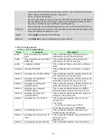
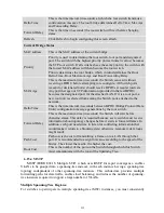
Current Bridge Status
MAC address
This is the MAC address of the current bridge.
Priority
Priority is used in determining the root switch, root port and designated
port. The switch with the highest priority (lowest numeric value) becomes
the STP root switch. If all switches have the same priority, the switch with
the lowest MAC address will then become the root switch.
Priority determines the root bridge, which in turn determines the Root
Hello Time, Root Maximum Age and Root Forwarding Delay.
MAX Age
This is the maximum time (in seconds) the Switch can wait without
receiving a BPDU before attempting to reconfigure. All Switch ports
(except for designated ports) should receive BPDUs at regular intervals.
Any port that age out STP information (provided in the last BPDU)
becomes the designated port for the attached LAN. If it is a root port, a
new root port is selected from among the Switch ports attached to the
network.
Hello Time
This is the time interval in seconds between BPDU (Bridge Protocol Data
Units) configuration message generations by the root switch.
Forward Delay
This is the maximum time (in seconds) the Switch will wait before
changing states. This delay is required because every switch must receive
information about topology changes before it starts to forward frames. In
addition, each port needs time to listen for conflicting information that
would make it return to a blocking state; otherwise, temporary data loops
might result.
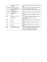
Path Cost
Path cost is the cost of transmitting a frame on to a LAN through that
port. It is recommended to assign this value according to the speed of the
bridge. The slower the media, the higher the cost.
Root Cost
This is the number of the port on the Switch through which this Switch
must communicate with the root of the Spanning Tree.
6.15.4
MSTP
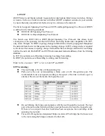
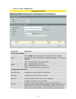
MSTP (IEEE 802.1S Multiple STP), which uses RSTP for rapid convergence, enables
VLANs to be grouped into a spanning-tree instance, with each instance having a spanning-tree
topology independent of other spanning-tree instances. This architecture provides multiple
forwarding paths for data traffic, enables load balancing, and reduces the number of spanning-
tree instances required to support a large number of VLANs.
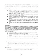
Multiple Spanning-Tree Regions:
For switches to participate in multiple spanning-tree (MST) instances, you must consistently
Summary of Contents for NGI-M08C4POE8-2
Page 1: ......
Page 197: ...197 Clear Clear the statistics of the valn ...
Page 298: ...298 9 2 2 Web Configurations ...


