12A
Service
If you are returning your Inverter/Charger to Tripp Lite, please pack it carefully, using the ORIGINAL PACKING MATERIAL that came
with the unit. Enclose a letter describing the symptoms of the problem. If the Inverter/Charger is within the warranty period, enclose a copy
of your sales receipt. To obtain service you must obtain a Returned Material Authorization (RMA) number from Tripp Lite or an author-
ized Tripp Lite service center.
Your Inverter/Charger requires no maintenance and contains no user-serviceable or replaceable parts, but should be kept dry at all times.
Periodically check, clean and tighten all cable connections as necessary, both at the unit and at the battery.
Try these remedies for common Inverter/Charger problems before calling for assistance. Call Tripp Lite Customer Service at (773) 869-1234
before returning your unit for service.
Maintenance
Troubleshooting
SYMPTOM
PROBLEMS
CORRECTIONS
No AC Output
Unit is not properly connected to utility power.
Connect unit to utility power.
(All Indicator Lights Are OFF)
Operating Mode Switch is set to “OFF” and
Set Operating Mode Switch to “AUTO/REMOTE” or “CHARGE ONLY.”
AC input is present.
This is normal when the Operating Mode Switch
No correction is required. AC output will return when AC input
is set to “CHARGE ONLY” and AC input is absent.
returns. Set Operating Mode Switch to “AUTO/REMOTE” if you
require AC output.
Circuit breaker is tripped.
Reset circuit breaker.
Unit has shut down due to battery overcharge (preventing
Disconnect any auxiliary chargers. Reset by moving Operating
battery damage). The problem may be with connected
Mode Switch to “OFF.” Wait 1 minute and switch to “AUTO/REMOTE”
auxiliary chargers, if any, or with the unit’s charger.
or “CHARGE ONLY.” If unit remains in shutdown mode after several
attempts to reset, contact Tripp Lite Customer Service for assistance.
Unit has shut down due to excessive battery discharge.
Use an auxiliary charger* to raise battery voltage. Check external
battery connections and fuse. Unit automatically resets when
condition is cleared.
Unit has shut down due to overload.
Reduce load. Reset by moving Operating Mode Switch to “OFF.”
Wait 1 minute. Switch to “AUTO/REMOTE” or “CHARGE ONLY.”
Battery Not Recharging
Connected batteries are dead.
Check and replace old batteries.
(AC Input Present)
Battery fuse* is blown.
Check and replace fuse.*
Battery cabling* is loose.
Check and tighten or replace cabling.*
Unit has shut down due to battery overcharge (preventing
Disconnect any auxiliary chargers. Reset by moving Operating Mode
battery damage). The problem may be with connected
Switch to “OFF.” Wait 1 minute and switch to “AUTO/REMOTE” or
auxiliary chargers, if any, or with the unit’s charger.
“CHARGE ONLY.” If unit remains in shutdown mode after several
attempts to reset, contact Tripp Lite Customer Service for assistance.
Input circuit breaker is tripped.
Reset circuit breaker.
All Three Battery Indicator Lights
Battery is excessively discharged.
Use an auxiliary charger* to raise battery voltage. Check external
Are Slowly Flashing
battery connections and fuse. Unit automatically resets when
(½ Second Flashes)
condition is cleared.
All Three Battery Indicator Lights
Battery is overcharged. Unit will shut down to prevent
Disconnect any auxiliary chargers. Reset by moving Operating Mode
Are Rapidly Flashing
battery damage. The problem may be with connected
Switch to “OFF.” Wait 1 minute and switch to “AUTO/REMOTE”
(¼ Second Flashes)
auxiliary chargers, if any, or with the unit’s charger.
or “CHARGE ONLY.” If unit remains in shutdown mode after several
attempts to reset, contact Tripp Lite Customer Service for assistance.
Red “LOW” Battery
Battery voltage is low. Unit will automatically shut down
Make sure that AC power is present in order to recharge batteries.
Indicator Light is Flashing
after 5 seconds to protect battery from damage.
Reset by moving Operating Mode Switch to “OFF then to
“AUTO/REMOTE” or “CHARGE ONLY.”
False reading due to undersized or insufficiently connected
Use sufficient size DC cable sufficiently connected to the
DC cabling.
Inverter/Charger.
Red “LOAD” Operation
Inverter is overloaded. Unit will automatically shut down
Reduce load. Reset by moving Operating Mode Switch to “OFF.”
Indicator Light Flashing
after 5 seconds.
Wait 1minute. Switch to “AUTO/REMOTE” or “CHARGE ONLY.”
Green “BOOST” or “CUT” Indicator Lights
This is a normal function.
No action is required on the user’s part.
(available on select models) Flashing
* User-supplied.
OFF
(LESSER
LOAD
ON)
MAX
(GREATER
LOAD
ON)
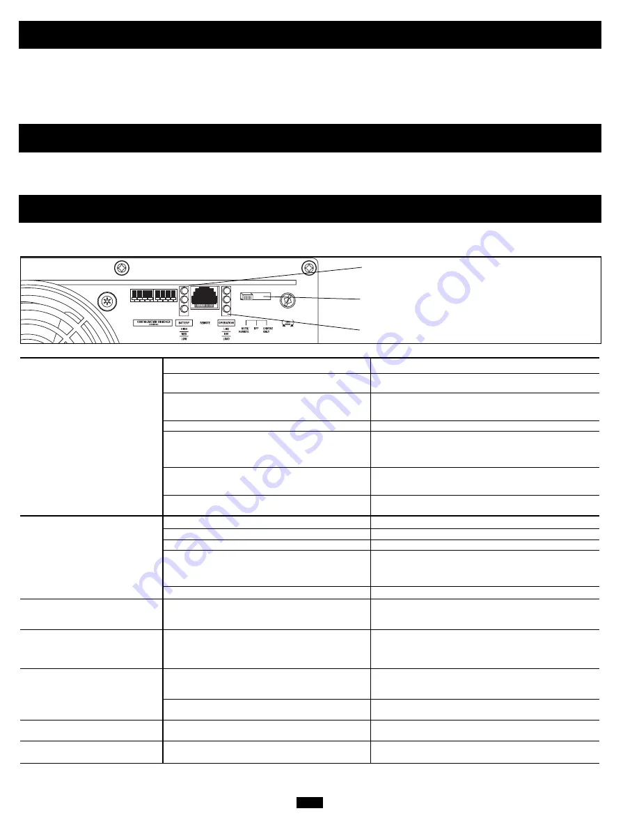
Battery Indicator Lights
Operating Mode Switch
Operation Indicator Lights
200407140 120V APS Owner’s Manual.qxd 9/16/2004 9:58 AM Page 12


