background image

3A

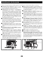
Feature Identification

Identify the premium features on your specific model and quickly locate instructions on how to maximize their use.

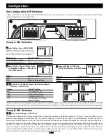
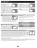
Configuration DIP Switches:

optimize Inverter/Charger 

operation depending on your application. See Configuration
Section for setting instructions. 

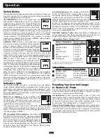
Operating Mode Switch:

controls Inverter/Charger operation.

The “AUTO/REMOTE” setting ensures your equipment
receives constant, uninterrupted AC power. It also enables the 
Inverter/Charger to be remotely monitored and controlled with
an optional remote module (Tripp Lite model APSRM4, sold 
separately). The “CHARGE ONLY” setting allows your batter-
ies to return to full charge faster by turning the inverter off
which halts battery discharging. See Operation Section for set-
ting instructions.

Operation Indicator Lights:

intuitive “traffic light” signals 

show whether the Inverter/Charger is operating from AC line 
power or DC battery power. It also warns you if the connected 
equipment load is too high. See Operation Section for instruc-
tions on reading indicator lights.

Battery Indicator Lights:

intuitive “traffic light” signals show 

approximate charge level of your battery. See Operation Section
for instructions on reading indicator lights.

DC Power Terminals:

connect to your battery terminals. See 

Battery Connection Section for connection instructions.

AC Output Receptacles (not on hardwire models): 

IEC-320

output receptacle(s) allow you to connect equipment that you
would normally plug into a utility outlet. Select models also
include a Universal AC Output Adapter which allows you to
connect equipment with a wide variety of plug styles.

AC Input Receptacle (not on hardwire models): 

IEC-320

input receptacle connects the Inverter/Charger to any source of
utility or generator-supplied AC power when used with a user-
supplied cable with country-specific plug.

Hardwire AC Input/Output Terminal Strip (not on corded
models):

securely connects the Inverter/Charger to facility or

vehicle electrical system. See Input/Output Connection Section
for connection instructions.

Resettable Circuit Breakers:

protect your Inverter/Charger 

against damage due to overload. See Operation Section for
resetting instructions.

Remote Control Module Connector:

allows remote monitoring 

and control with an optional module (Tripp Lite model
APSRM4, sold separately). See remote module owner’s manu-
al for connection instructions.

Battery Charge Conserver (Load Sense) Control (available
on select models):

conserves battery power by setting the 

low-load level at which the Inverter/Charger’s inverter automati-
cally shuts off. See Configuration Section for setting instructions.

Main Ground Lug:

properly grounds the Inverter/Charger to

earth ground or to vehicle or boat grounding system. See Battery
Connection Section for connection instructions.

Thermostatically-Controlled Cooling Fan:

quiet, efficient fan 

regulates internal temperature and prolongs equipment service
life. Fan runs intermittently depending on temperature and load.

DC Power Terminal Cover Plate

Hardwire AC Input/Output Cover Plate

Dead Battery Startup Feature (for all models, internal, not
shown): 

internal circuitry allows you to start up the

Inverter/Charger even with a dead battery connected to the unit.
As long as the Inverter/Charger is connected to a live utility- or
generator-supplied AC power source, the Inverter/Charger will
pass through AC power to connected equipment and charge con-
nected batteries.

1

2

3

4

5

6

7

8

9

10

11

12

13

14

15

HOT    IN

NEUTRAL    IN

GROUND    IN

GROUND    OUT

HOT    OUT

“FOR USE WITH COPPER WIRE ONLY”

NEUTRAL    OUT

1

2

4

3

5

9

10

11

13

14

8

15

Front View (2012 & 2424 Hardwire Models).

16

Side Mounted, Not Shown

12

Rear Mounted, Not Shown

Front View (750 & 1250 Corded Model)

1

2

4

3

5

6

9

10

13

7

12

200407145 93-2274 230V APS 4 language.qxd  3/28/2005  4:02 PM  Page 3

Summary of Contents for PowerVerter APSX

Page 1: ...e Protection Automatic Overload Protection Ideal Output for All Loads including computers Frequency Controlled Output Fast Load Switching Balanced Load Sharing Better for Your Batteries Faster Battery...

Page 2: ...r will cause it to short circuit and could cause personal injury due to electric shock Never immerse the unit and avoid any area where standing water might accumulate Mounting should be in the driest...

Page 3: ...AC power when used with a user supplied cable with country specific plug Hardwire AC Input Output Terminal Strip not on corded models securely connects the Inverter Charger to facility or vehicle ele...

Page 4: ...CHARGE ONLY this light will FLASH to alert you that the unit s inverter is OFF and will NOT supply AC power in the absence of a utility generator source or in over under voltage situations INV Invert...

Page 5: ...oint and or decreasing the Low AC Voltage Point you will reduce the number of times your unit switches to battery due to voltage swings Group B DIP Switches Select Load Sharing OPTIONAL Your Inverter...

Page 6: ...ly from full output at 33 of the Inverter Charger s load rating to about 33 of full output at full load Least Limiting B1 Up B2 Down Charger limiting begins at when the Inverter Charger s load reaches...

Page 7: ...ur batteries with utility or genera tor supplied AC power Compensate for inefficiency by multiplying this number by 1 2 This will give you a rough estimate of how many amp hours of battery power from...

Page 8: ...over the fasteners to engage the mounting feet molded on the front of the Inverter Charger cabinet Install and tighten two user supplied 6 mm fasteners into the mounting feet molded on the rear of th...

Page 9: ...g Though your Inverter Charger is a high efficiency con verter of electricity its rated output capacity is limited by the length and gauge of the cabling run ning from the battery to the unit Use the...

Page 10: ...e over the hardwire terminal box Remove the knockout covers closest to the desired electrical source and to your equipment Attach 1 28 cm diameter conduits user supplied to the knockouts and thread wi...

Page 11: ...e fuse Battery cabling is loose Check and tighten or replace cabling Unit has shut down due to battery overcharge preventing Disconnect any auxiliary chargers Reset by moving Operating Mode battery da...

Page 12: ...ensiones integrada Isobar Protecci n autom tica contra sobrecarga Salida ideal para cualquier carga incluyendo computadoras Salida controlada por frecuencia R pida conmutaci n de carga Reparto de carg...

Page 13: ...choque el ctrico Nunca sumerja la unidad y evite toda rea donde pueda acumularse agua El montaje debe realizarse en la ubicaci n m s seca disponible Deje una luz m nima de 5 cm en la parte frontal y p...

Page 14: ...dor cuando se emplea con un cable suministrado por el usuario con alg n enchufe de uso local especial Regleta cableada de terminales de entrada salida de corri ente alterna no en modelos con cord n Co...

Page 15: ...e NO suministrar energ a de corriente alterna en ausencia de alimentaci n de la red o de un generador o en casos de sobrevoltaje o bajo voltaje Indicador INV Inversi n amarillo Esta luz se ILUMINAR CO...

Page 16: ...idad de veces que su unidad cambia a bater a debido a variaciones de voltaje Conmutadores DIP Grupo B Seleccionar reparto de carga OPCIONAL Su inversor cargador presenta un cargador de bater a de alta...

Page 17: ...alida completa a plena carga M nima limitaci n B1 arriba y B2 abajo La limitaci n del cargador comien za cuando la carga del inversor cargador alcanza el 66 de su capacidad total de carga La salida de...

Page 18: ...por 1 2 Esto le dar un estimado grueso de cuantos amperios hora de energ a de bater a de una o varias bater as debe conectar a su inversor cargador NOTA La capacidad de amperios hora de una bater a u...

Page 19: ...a adelante sobre los tornillos para enganchar la base de montaje moldeada en la parte frontal del gabinete del inversor car gador Instale y apriete dos tornillos de 6 mm suministra dos por el usuario...

Page 20: ...cia su capacidad de salida est limitada por la longitud y el calibre del cableado desde la bater a hasta la unidad Use la longitud m s corta y el calibre de mayor di metro del cableado m ximo calibre...

Page 21: ...s cubiertas de los agujeros ciegos m s cercanas a la fuente el ctrica deseada y a su equipo Conecte tubos de 1 2 de di metro suministrados por el usuario a los agujeros ciegos y pase los conductores a...

Page 22: ...Revise y reemplace el fusible El cableado de la bater a est flojo Revise y ajuste o reemplace el cableado La unidad se ha apagado debido a sobrecarga de la bater a Desconecte cualquier cargador auxili...

Page 23: ...ons Protection automatique contre les surcharges Sortie id ale pour toutes les charges y compris les ordinateurs Sortie fr quence contr l e Commutation rapide de la charge Partage quilibr e de la char...

Page 24: ...lectrique Ne jamais immerger l unit et viter toute zone o pourrait s accumuler de l eau stagnante Le montage doit se faire l emplacement le plus sec possible Maintenez un d gagement minimal de 5 cm l...

Page 25: ...rice l aide d un c ble quip d une fiche sp cifique au pays fourni par l utilisateur Barrette raccordement fixe de bornes d entr e de sortie CA pas sur les mod les cordon Connecte s curitairement l ond...

Page 26: ...us avertir que l onduleur de l unit est OFF ferm et Ne fournira Pas de courant CA en l absence d une source du secteur ou d une g n ratrice ou dans des situations de basse ou haute tension Voyant jaun...

Page 27: ...e tension d entr e CA ou en abaissant le point bas de tension d entr e CA vous r duirez le nombre de fois o votre unit passera sur batterie cause de variations de tension Groupe B de commutateurs DIP...

Page 28: ...de l onduleur chargeur environ 33 de la sortie pleine pleine charge Limitation minimale No B1 en haut ET No B2 en bas La limitation du chargeur commence lorsque la charge de l ond uleur chargeur atte...

Page 29: ...ne estimation grossi re de la puissance de batterie en A h d une ou de plusieurs batteries que vous devrez brancher votre CO REMARQUE La puissance nominale en A h des batteries est habituellement donn...

Page 30: ...l s en avant du bo tier de l onduleur chargeur Installer et serrer deux attaches de 6 mm po fourni par l utilisateur dans les pieds de montage moul s en avant du bo tier de l onduleur chargeur Les pie...

Page 31: ...argeur est un c o n v e r t i s s e u r hautement efficace d lectricit sa puissance nominale de sortie est limit e par la longueur et le calibre des connecteurs CC du c blage reliant la batterie l uni...

Page 32: ...t le couvercle de la bo te de bornes raccordement fixe Enlever les entr es d fon ables les plus proches de la source lectrique d sir e et de votre quipement Fixer des tubes protecteurs de 1 28 cm de d...

Page 33: ...e a saut V rifier et remplacer le fusible Le c blage de la batterie est l che V rifier et resserrer ou remplacer le c blage L unit s est teinte cause d une surcharge emp chant des D brancher tous les...

Page 34: ...lish 1 Espa ol 12 Fran ais 23 PowerVerter APSX 12 24 230 50 230 50 12 24 1111 W 35th Street Chicago IL 60609 USA 773 869 1212 www tripplite com 750 1250 2005 PowerVerter Tripp Lite Tripp Lite APS Auto...

Page 35: ...Tripp Lite Tripp Lite Tripp Lite RMA Returned Material Authorization Tripp Lite Tripp Lite 10 TRIPP LITE TRIPP LITE Tripp Lite Tripp Lite Tripp Lite 5 APS Tripp Lite APS Tripp Lite UPS Uninterruptibl...

Page 36: ...ONLY IEC 320 IEC 320 Tripp Lite APSRM4 1 2 3 4 5 6 7 8 9 10 11 12 13 14 15 HOT IN NEUTRAL IN GROUND IN GROUND OUT HOT OUT FOR USE WITH COPPER WIRE ONLY NEUTRAL OUT 1 2 4 3 5 9 10 11 13 14 8 15 2012 2...

Page 37: ...ONLY OFF OFF AUTO REMOTE CHARGE ONLY Tripp Lite APSRM4 Tripp Lite LINE AUTO REMOTE CHARGE ONLY INV LOAD 100 OFF AUTO REMOTE CHARGE ONLY BATTERY 91 81 90 61 80 41 60 21 40 1 20 0 OFF AUTO REMOTE CHARGE...

Page 38: ...A2 A3 A4 INPUT C B 10A OUTPUT C B 12A B4 B3 B2 B1 A4 A3 A2 A1 D DI IP P B B D DI IP P A A DIP A 201 A4 A3 182 A4 A3 163 A4 A3 144 A4 A3 182 DIP B DIP A1 A2 A3 A4 B2 B1 B B B B APSX2424 278 259 APSX750...

Page 39: ...ualize Reset DIP 3 B1 B2 230 B1 B2 33 33 33 B1 B2 66 66 66 B1 B2 B1 B2 B3 B4 B1 B2 B3 B4 B1 B2 B3 B4 B1 B2 B3 B4 B1 B2 B3 B4 750 1250 8 Tripp Lite APSRM4 B1 B2 B3 B4 OFF LESSER LOAD ON MAX GREATER LOA...

Page 40: ...40A 6 Marine 8D DIP Tripp Lite 1 1 3 1 3 230 300 75 80 2 1 12 24 3 2 1 2 20 55 50 9 30 4 3 Tripp Lite 1000 Tripp Lite Tripp Lite 300 220 20 540 300 140 100 540 540 12 45 45 5 1 2 270 270 30 9...

Page 41: ...Tripp Lite Tripp Lite 750 1250 6 6 2012 2424 6 6 A B C A B C A C B M A C B M 2012 2424 Tripp Lite Tripp Lite Tripp Lite APS A C B M M M M M M 11 4 cm 17 1 cm 20 cm 14 16 cm 38 12 cm M M M M M M M M 38...

Page 42: ...42A 12 24 12 24 12 12 12 24 24 12 24 2 12 6 24 4 6 12 Tripp Lite X 12 24 UL 45 2 0 5 4 3 2 1 XB XB 4 1 2 3 24B 6B 6B 6B 6B 1 2 2 2 2 4 3 5 2 0 200 3 5 8 AWG American Wire Gage Tripp Lite 45 18...

Page 43: ...43A 100 IEC 320 IEC 320 1 28 HOT IN NEUTRAL IN GROUND IN GROUND OUT HOT OUT FOR USE WITH COPPER WIRE ONLY NEUTRAL OUT 2 3 1 4 5 1 2 3 4 5 DoubleBoostTM Tripp Lite 10 OverPowerTM Tripp Lite 1 150...

Page 44: ...EMOTE CHARGE ONLY CHARGE ONLY AUTO REMOTE OFF 1 AUTO REMOTE CHARGE ONLY Tripp Lite OFF 1 AUTO REMOTE CHARGE ONLY OFF 1 AUTO REMOTE CHARGE ONLY Tripp Lite OFF 1 AUTO REMOTE CHARGE ONLY Tripp Lite LOW 5...

Page 45: ...Selectable Wet Gel Float Volts VDC Wet Gel 13 3 V 13 6 V 13 3 V 13 6 V 13 3 V 13 6 V 26 6 V 27 2 V Input Current AC Maximum 2 A 3 A 7 A 7 A LINE VAC OPERATION Common Specifications for All Models Mini...

Page 46: ...el producto 1111 W 35th Street Chicago IL 60609 U S A 773 869 1234 www tripplite com Sp cifications Remarque sur l tiquetage Deux symboles sont utilis s sur les tiquettes d APS V Tension CA Tension CC...

Reviews: