7
AC Connection
To avoid overloading your Inverter/Charger, be sure to match the power requirements of the equipment
you plan to run at any one time (add the total watts) with the continuous output capacity of your
Inverter/Charger (see the
Specifications
section). When figuring the power requirements of your
equipment, do not confuse continuous wattage with peak wattage ratings. Most electric motors require
more power at start-up (peak wattage) than required to run continuously after start-up, sometimes over
100% more. Some motors, such as in refrigerators and pumps, start and stop intermittently according to
demand, requiring peak wattage at multiple, unpredictable times during operation.
Your Inverter/Charger has an IEC 60320 C14 input connector and an IEC 60320 C13 output connector
(see the Features section for more information). Attach the input connector to a user-supplied cable with
a plug appropriate for the local site, and plug the Inverter/Charger to a utility wall outlet that provides
230 V, 50 Hz AC power. Use the output connector to power equipment that would normally be plugged
into a utility outlet. Any equipment you plug into the output connector automatically benefits from your
Inverter/Charger's
Isobar
®
surge protection.
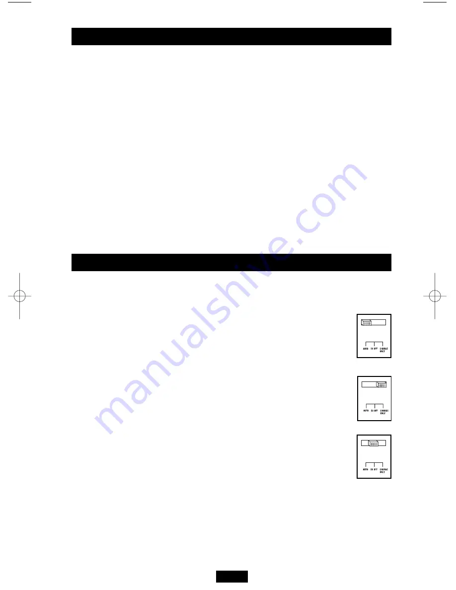
After mounting and connecting your Inverter/Charger, you are able to operate it by switching between
operating modes as appropriate to your situation.
“AUTO”:
Switch to this mode when you need constant, uninterrupted AC power for
connected equipment. The Inverter/Charger will supply AC power to connected equipment
and charge your connected batteries while utility or generator-supplied AC power is
present. The Inverter/Charger will automatically switch to battery to supply AC power to
connected equipment when utility/generator power is unavailable or unsafe for connected
equipment.
“CHARGE ONLY”:
Switch to this mode when you are not using connected equipment in
order to conserve battery power by disabling the inverter. The Inverter/Charger will supply
AC power to connected equipment and charge connected batteries while utility- or
generator-supplied AC power is present. However, it WILL NOT supply AC power to
connected equipment when utility/generator power is unavailable or unsafe for connected
equipment.
“DC OFF”:
Switch to this mode to prevent the inverter from drawing power from the
batteries. Use this mode to automatically reset the unit if it shuts down due to overload or
overheating. First remove the excessive load or allow the unit to sufficiently cool, as
applicable. Switch to “DC OFF”, then back to “AUTO” or “CHARGE ONLY” as desired.
If the unit fails to reset, remove more load or allow the unit to cool further and try again.
Caution: The unit will always pass AC power to connected equipment if plugged into a live AC
outlet, regardless of the position of the Operating Mode Switch.
Operation
Switch Modes
200705102 93-2678 APSX700HF OM.qxd 8/30/2007 12:34 PM Page 7


