background image

3

Equipment Connection

Plug your equipment into the Power Strip’s AC receptacles. DO NOT plug in equipment that draws 
more total amps than your Power Strip’s amperage rating (see label on Power Strip for amperage 
rating), or you will trip the circuit breaker. If the circuit breaker trips, remove overload and depress 

breaker to reset. Leave enough clearance at the end of the Power Strip to allow the circuit 
breaker to operate normally.

Note:

 Select models with a power switch feature a protective switch cover. To access the switch, flip open the 

attached cover.

Wall Mounting

All Power Strip models feature clips for horizontal or vertical mounting on a variety of surfaces.
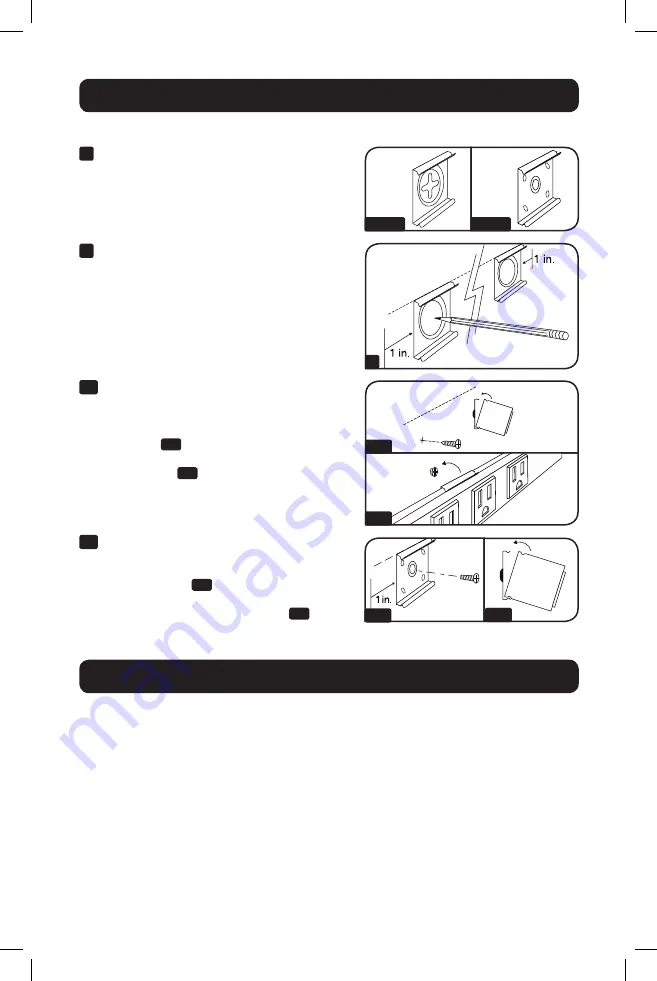
1


Check Clip Type:

 Your Power Strip will contain 

one of two types of mounting clips, depending 
on the model.

2

  Mark a straight horizontal or vertical line where 

you want to mount the Power Strip. At each end 
of the line, mark where the edges of the Power 
Strip will be located. Place a mounting clip on 
the mounting surface 1” in from these edges 

and mark where the screws must be driven into 
the wall. For strips longer than 48” (120 cm), 
also mark a screw hole for a third mounting clip 

midway between the other two.

3a

 Clip-A  Mounting:

 Drive #8 screws directly into 

the mounting surface, leaving approximately 
3 mm of space between the screw head and 
the surface. Snap the mounting clips onto the 

Power Strip 

3a1

, then hang the Power Strip 

on the screws by the keyhole slots on its 

mounting clips 

3a2

.

3b

 Clip-B  Mounting: 

Pre-drill holes in the mounting 

surface, if necessary. Drive screws through 
the centers of the mounting clips and into the 

mounting surface 

3b1

. Place the Power Strip 

inside one edge of the mounting clips, 
then snap the Power Strip into place 

3b2

.

2

3b1

3b2

3b2

3a1

3a2

Clip-A

Clip-B

19-03-135-933971.indb   3

4/4/2019   11:02:36 AM

Summary of Contents for PSC240410USBB

Page 1: ...quipment with surge or line noise protection Important Safety Instructions 2 Clamp Mounting 2 Wall Mounting 3 Equipment Connection 3 Warranty and Product Registration 4 Espa ol 5 Fran ais 9 WARRANTY R...

Page 2: ...of this equipment in life support applications where failure of this equipment can reasonably be expected to cause the failure of the life support equipment or to significantly affect its safety or ef...

Page 3: ...tal or vertical line where you want to mount the Power Strip At each end of the line mark where the edges of the Power Strip will be located Place a mounting clip on the mounting surface 1 in from the...

Page 4: ...itation of incidental or consequential damages so the above limitations or exclusions may not apply to you This Warranty gives you specific legal rights and you may have other rights which vary from j...

Page 5: ...Manual del Propietario Nota Los modelos de Barra de Contactos NO proporcionan a su equipo conectado protecci n contra sobretensiones o ruido en la l nea Instrucciones de Seguridad Importantes 6 Soport...

Page 6: ...en aplicaciones de soporte de vida en donde razonablemente se pueda esperar que la falla de este equipo cause la falla del equipo de soporte de vida o afectar significativamente su seguridad o efecti...

Page 7: ...instalar la barra de contactos En cada extremo de la l nea marque en donde se localizar n los bordes de la Barra de Contactos Coloque un clip de instalaci n en la superficie de instalaci n a 1 desde...

Page 8: ...INDIRECTOS Algunos estados no permiten limitaciones en cuanto dura una garant a y algunos estados no permiten la exclusi n de limitaci n de da os incidentales o indirectos de modo que las limitaciones...

Page 9: ...s Manuel de l utilisateur Remarque Les mod les de barres d alimentation N OFFRENT PAS de protection contre les surtensions ou les bruits l quipement connect Consignes de s curit importantes 10 Montag...

Page 10: ...est pas recommand d utiliser cet quipement pour des appareils de survie o une d faillance de cet quipement peut selon toute vraisemblance entra ner la d faillance de l appareil de maintien de la vie...

Page 11: ...endroit o la barre d alimentation sera mont e chacune des extr mit s de la ligne marquer l endroit o se situeront les bords de la barre d alimentation Placer une agrafe de montage sur la surface de m...

Page 12: ...permettent pas de limitations sur la dur e d une garantie implicite et certains tats ne permettent pas l exclusion ou la limitation des dommages fortuits ou cons cutifs de sorte que les limitations ou...

Reviews: