background image

4

2. Important Safety Warnings

SAVE THESE INSTRUCTIONS 

This manual contains important instructions and warnings that should be followed during the installation and maintenance 

of all Tripp Lite SmartOnline S3MX 3-Phase 30kVA, 40kVA, 60kVA and 80kVA UPS Systems and their batteries. Failure to 

heed these warnings may affect your warranty.

2.1 UPS Location Warnings

• Install the UPS indoors, away from heat, direct sunlight, dust and excess moisture or other conductive contaminants.
• Install the UPS in a structurally sound area. The UPS is extremely heavy; take care when moving and lifting the unit.
• Only operate the UPS at indoor temperatures between 0° C and 40° C.
• Optimum UPS performance and maximum battery life is obtained when the operating temperature is maintained between  

17° C and 25° C.

• Ensure the installation area has sufficient space for maintenance and ventilation of the UPS system. Maintain a minimum clearance of  

50 cm from the rear, front and both sides of the UPS for maintenance and ventilation.

• Do not install the UPS near magnetic storage media, as this may result in data corruption.

2.2 Equipment Connection Warnings

• Use of this equipment in life support applications where failure of this equipment can reasonably be expected to cause the failure of the 

life support equipment or to significantly affect its safety or effectiveness is not recommended. 

• The UPS system contains its own energy source (battery). The output terminals may be live even when the UPS is not connected to an 

AC supply.

2.3 Battery Warnings

 This UPS contains LETHAL VOLTAGES. The UPS is designed to supply power, even when disconnected from utility power. Only 

AUTHORISED SERVICE PERSONNEL should access the interior of the UPS after disconnecting utility and DC power.

 Batteries present a risk of electrical shock and burns from high short-circuit current. Battery connection or replacement should be 

performed only by qualified service personnel, observing proper precautions. Turn off the UPS before connecting or disconnecting 

internal batteries. Use tools with insulated handles. Do not open the batteries. Do not short or bridge the battery terminals with any 
object.

• The batteries are recyclable. Refer to local codes for disposal requirements or visit http://www.tripplite.com/support/recycling-program for 

recycling information.

• Do not dispose of the batteries in a fire, mutilate the batteries or open the battery coverings. Escaping electrolytes may be toxic and 

cause injury to skin and eyes.

• Do not disconnect the batteries while the UPS is in battery mode.
• Disconnect the charging source prior to connecting or disconnecting terminals.
• The following precautions should be observed:

1)  Remove watches, rings and other metal objects.
2)  Use tools with insulated handles.
3)  Wear rubber gloves and boots.
4)  Do not lay tools or metal parts on top of batteries or battery cabinets.
5)  Determine whether the battery supply (+, -, N) is inadvertently grounded. If it is, remove the source of the ground. Contact with any 

part of a grounded battery can result in electric shock. The likelihood of an electric shock is reduced if such grounds are removed 

during installation and maintenance.

• Battery replacement should be performed only by authorised service personnel, using the same number and type of batteries (sealed 

lead acid).

WARNING: In order to avoid any hazardous conditions during UPS installation and maintenance, these tasks may be 

performed only by qualified and experienced electricians.

Please read this Owner’s Manual and the safety instructions carefully before installing or using the unit.

Summary of Contents for S3M30KX

Page 1: ...3MX 3 Phase UPS Systems Models S3M30KX S3M40KX S3M60KX S3M80KX Input 220 230 240V Ph N 380 400 415V Ph Ph 3 4 Wire PE 1111 W 35th Street Chicago IL 60609 USA www tripplite com support Copyright 2018 T...

Page 2: ...ms 12 3 5 External Battery Connection 13 4 Operation 14 4 1 Display Button Operation 14 4 2 LED Indicators and LCD Panel 14 4 3 Audible Alarm 16 4 4 Single UPS Operation 16 4 5 Parallel UPS Operation...

Page 3: ...attery Standby Modes minimise energy consumption Market leading compact footprint so more power can be provided from smaller spaces ECO Mode allows the UPS to operate on bypass in stable utility condi...

Page 4: ...cess the interior of the UPS after disconnecting utility and DC power Batteries present a risk of electrical shock and burns from high short circuit current Battery connection or replacement should be...

Page 5: ...ed by qualified maintenance personnel An appropriate disconnect device such as short circuit backup protection must be provided in the building wiring installation An integral single emergency switchi...

Page 6: ...ble on the UPS or the building wiring terminals at any time as this will cancel the protective earth of the UPS system In order to fully disconnect the UPS system first press the OFF button then disco...

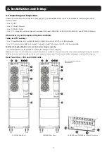
Page 7: ...being paralled One 1 shared current cable only available for parallel model for every set of UPS units being paralled Additional Charging Board to increase the battery charger capacity 4A charger boar...

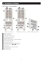
Page 8: ...4 Share Current Port for Paralleling Units 5 Parallel Ports for Paralleling Units 6 SNMP Slot for Network Monitoring using Optional WEBCARDLX 7 External Battery Cabinet Connector 8 Line Input Circuit...

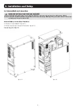
Page 9: ...d to a UPS system Battery connection should be performed by qualified service personnel only following all the precautions listed in this manual and adhering to local electrical codes Internal Battery...

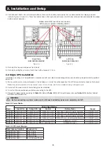
Page 10: ...e UPS 4 Prepare the power cables according to Table 3 1 Refer to Table 3 2 for UPS Input Breaker sizes and Table 3 3 for Battery Cabinet Batteries and Breaker sizes WARNING Before connecting any wires...

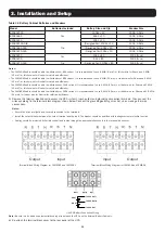
Page 11: ...al for safety and efficiency The S3M80KX cable should be able to withstand over 160A current It is recommended to use 2 AWG 34 mm2 or thicker wire for Phase and 1 0 AWG 54 mm2 or thicker wire for Neut...

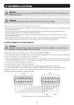
Page 12: ...ctance reliability should be checked carefully Make sure the R S T and N wiring is correct not reversed and not short circuited 3 4 UPS Installation for Parallel Systems If the UPS is only used for si...

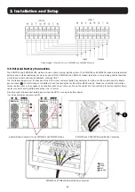
Page 13: ...connector for the 30K and 40K model where the battery pack connects 7 The illustration at the bottom shows the connection for the 60K and 80K models Follow the installation instructions for your batte...

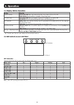
Page 14: ...ss and hold for more than 0 5 seconds to mute the alarm Refer to section 4 4 9 for details Down Button Press to display the previous selection in the settings menu Test Up Mute Down Button Press and h...

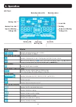
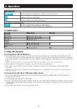
Page 15: ...age information Indicates the output voltage frequency or battery voltage VAC Output Voltage VDC Battery Voltage Hz Frequency Load information Indicates the load level by 0 25 26 50 51 75 and 76 100 I...

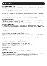
Page 16: ...in Bypass Mode and supply power to the connected loads via the bypass Note In Bypass Mode the load is not protected by the UPS To protect connected devices turn on the UPS as shown in Step 2 2 Press...

Page 17: ...ry discharge protection can be enabled or disabled through the LCD control panel refer to section 4 7 for more information 4 4 6 Testing the Batteries 1 To check the battery status when the UPS is in...

Page 18: ...peration 4 5 1 Parallel System Initial Startup Before initial startup ensure all UPS systems have the same configuration and can be connected in parallel 1 Turn on each UPS to On line Mode refer to se...

Page 19: ...re are two methods to remove a unit from the parallel system Method 1 1 Press the OFF key twice each time for more than 0 5 seconds The UPS will enter into Bypass Mode or Standby Mode without output 2...

Page 20: ...rst line ST The second line TR The third line HS H Hot standby 4 7 Setup Menu Press and hold the Test Up and Mute Down buttons simultaneously for longer than one second to enter exit the Setup Menu Th...

Page 21: ...ustment Y Y Y Y Y Y 15 Inverter A voltage adjustment Y Y Y 16 Inverter B voltage adjustment Y Y Y 17 Inverter C voltage adjustment Y Y Y 18 Output A voltage calibration Y Y Y 19 Output B voltage calib...

Page 22: ...t within 46 54 Hz If 60 Hz is selected in Parameter 2 the UPS will transfer to Battery Mode when the input frequency is not within 56 64 Hz If Parameter 2 is ATO Parameter 3 will show the current freq...

Page 23: ...meter 2 OPN Bypass allowed When selected the UPS will run in Bypass Mode depending on whether the bypass setting is enabled disabled FBD Bypass not allowed When selected Bypass Mode is not allowed in...

Page 24: ...cted an alarm will be generated If the UPS is turned on it will transfer to Battery Mode When neutral is restored the alarm will NOT be muted automatically and the UPS will NOT return to Normal Mode a...

Page 25: ...voltage 18 Output A Voltage Calibration Interface Setting Parameter 2 Always shows OP V as output voltage Parameter 3 Shows the internal measurement value of the output A voltage You can calibrate it...

Page 26: ...will charge the battery at the maximum power of 4A current Extension board kits are available for the S3M30KX and S3M40KX models CBKIT30 40 and the S3M60KX and S3M80KX models CBKIT30 80 22 Charging B...

Page 27: ...ss voltage frequency is out of acceptable range or bypass is disabled or forbidden the UPS will enter No output Mode if powering on or turning off the UPS This means the UPS has no output The alarm wi...

Page 28: ...28 AC Mode continued ECO Mode Description When the input voltage is within voltage regulation range and ECO Mode is enabled UPS will bypass voltage to output for energy saving LCD Panel 4 Operation...

Page 29: ...50 Hz or 60 Hz In this mode the UPS will have no bypass output but still charge the battery LCD Panel Battery Mode Description When the input voltage frequency is beyond the acceptable range or exper...

Page 30: ...ll enter Bypass Mode The alarm will beep every two minutes LCD Panel Battery Test Description When the UPS is in AC Mode or CVCF Mode press the Test button for more than 0 5 seconds The UPS will beep...

Page 31: ...icon will be flashing It can show up to 3 error codes with each code indicating one error The code meaning can be found in the warning code table in section 4 11 LCD Panel Fault Status Description Whe...

Page 32: ...utput line to line short circuited 66 Inverter current sample abnormal None 19 Inverter T R output line to line short circuited 67 Bypass O P short circuited 1A Inverter A negative power fault None 68...

Page 33: ...show a warning In the warning screen the icon will flash Up to three error codes may display with each code indicating one error Warning Code Warning Event Warning Code Warning Event 01 Battery disco...

Page 34: ...plite com for further details Note Only one card may be used at a time 5 2 EPO Connector The EPO is included as standard for site safety Its default setting is Normally Closed N C with pins 1 and 2 cl...

Page 35: ...LCD The alarm beeps continuously UPS is overloaded for too long and becomes fault The UPS automatically shuts down Remove excess loads from the UPS output and restart Fault code is shown as 14 15 16...

Page 36: ...The battery circuit is not isolated from the input voltage Hazardous voltages may occur between the battery terminals and the ground Batteries may cause electric shock and have a high short circuit c...

Page 37: ...0 s 130 1 s Current Crest Ratio 3 1 Maximum Harmonic Distortion 100 Load 2 THD Linear Load 4 THD Non Linear Load Transfer Time Line Battery 0 ms Transfer Time Inverter Bypass Synchronous 0 ms Asynchro...

Page 38: ...a wide range of Network Management Systems and DCIM platforms Control Panel 62 mm LCD with supplemental LEDs Contact Closure Interface Requires Optional RELAYCARDSV Programmable Relay I O Card Remote...

Page 39: ...gned for 40 x 65Ah batteries includes battery cabling and breaker BP480V40 200A 3 Pole 1221 x 826 x 900 Battery Cabinet with 40 x 40Ah batteries BP480V40 NIB Battery Cabinet without batteries but desi...

Page 40: ...O EXPRESS WARRANTIES OTHER THAN THE WARRANTY EXPRESSLY SET FORTH HEREIN EXCEPT TO THE EXTENT PROHIBITED BY APPLICABLE LAW ALL IMPLIED WARRANTIES INCLUDING ALL WARRANTIES OF MERCHANTABILITY OR FITNESS...

Page 41: ...rif sicos Modelos S3M30KX S3M40KX S3M60KX S3M80KX Entrada 220V 230V 240V Fase Neutro 380V 400V 415V Fase Fase 3 4 Hilos Tierra F sica 1111 W 35th Street Chicago IL 60609 EE UU www tripplite com suppor...

Page 42: ...Conexi n de la Bater a Externa 53 4 Operaci n 54 4 1 Operaci n del Bot n de Pantalla 54 4 2 Indicadores LED y Panel LCD 54 4 3 Alarma Ac stica 56 4 4 Operaci n con Solo Un UPS 56 4 5 Operaci n del UP...

Page 43: ...la Bater a minimiza el consumo de energ a Tama o de base peque o l der en el mercado para m s potencia en espacios m s peque os El modo ECO permite al UPS operar en derivaci n en condiciones estables...

Page 44: ...r del UPS despu s de desconectar la energ a de la red p blica o de CD Las bater as presentan un riesgo de descarga el ctrica y quemaduras por la alta corriente de cortocircuito La conexi n y reemplazo...

Page 45: ...proporcionarse un dispositivo adecuado de desconexi n como protecci n de respaldo contra cortocircuito En la instalaci n de cableado del edifico debe incluirse un dispositivo integral nico de apagado...

Page 46: ...cable conductor de tierra en el UPS o las terminales de cableado del edificio ya que esto cancelar la conexi n protectora a tierra del sistema UPS A fin de desconectar completamente el sistema UPS opr...

Page 47: ...te s lo disponible para el modelo en paralelo para cada juego de unidades UPS que se est n conectando en paralelo Tarjeta de carga adicional para aumentar la capacidad de carga de la bater a Las tarje...

Page 48: ...orriente para Unidades en Paralelo 5 Puerto para Conexi n en Paralelo para Unidades en Paralelo 6 Ranura SNMP para Monitoreo de Red Usando WEBCARDLX Opcional 7 Conector de Gabinete de la Bater a Exter...

Page 49: ...n de la bater a debe realizarla solamente personal de servicio calificado siguiendo todas las precauciones listadas en este manual y observando todos los c digos el ctricos locales Procedimiento para...

Page 50: ...do con la Tabla 3 1 Refi rase a la Tabla 3 2 para consultar los tama os de breakers de alimentaci n y la Tabla 3 3 para los tama os de las bater as del Gabinete de Bater as y del Breaker ADVERTENCIA A...

Page 51: ...capaz de soportar una corriente superior a 160A Por seguridad y eficiencia es recomendable usar cable 2 AWG 34 mm2 o mayor por Fase y cable 1 0 AWG 54 mm2 para el Neutro 5 Retire la cubierta del bloqu...

Page 52: ...ficaci n de corriente del cable el color la posici n y la confiabilidad en la conductancia Cerci rese que est correcto el cableado R S T y N no invertido ni en cortocircuito 3 4 Instalaci n del UPS pa...

Page 53: ...K en donde se conecta el m dulo de bater as 7 La ilustraci n en la parte inferior muestra la conexi n para los modelos 80K y 60K Siga las instrucciones de instalaci n para su m dulo de bater as como a...

Page 54: ...detalles consulte la secci n 4 4 9 Bot n Down Abajo Oprima para mostrar la selecci n anterior en el men de par metros Botones Test Up Mute Down Oprima y sostenga simult neamente ambos botones por m s...

Page 55: ...e de la bater a VCA Voltaje de Salida VCD Voltaje de la Bater a Hz Frecuencia Informaci n de carga Indica el nivel de carga por 0 25 26 50 51 75 y 76 100 Indica sobrecarga Indica que la carga o la sal...

Page 56: ...rivaci n y alimentar a las cargas conectadas mediante la derivaci n Nota En el Modo en Derivaci n la carga no est protegida por el UPS Para proteger los dispositivos conectados encienda el UPS como se...

Page 57: ...ivarse o desactivarse mediante el panel LCD de control refi rase a la secci n 4 7 para informaci n adicional 4 4 6 Prueba de las Bater as 1 Para comprobar el estado de la bater a cuando el UPS est en...

Page 58: ...na unidad 4 5 Operaci n del UPS en Paralelo 3 5 1 Arranque Inicial de Sistema en Paralelo Antes del arranque inicial aseg rese de que todos los sistemas UPS puedan conectarse en paralelo y tengan la m...

Page 59: ...idad del Sistema en Paralelo Existen dos modos de retirar una unidad de un sistema en paralelo M todo 1 1 Oprima dos veces la tecla OFF cada vez durante m s de 0 5 segundos El UPS ingresar al Modo en...

Page 60: ...a ST La segunda l nea TR La tercera l nea HS H En Espera Activa 4 7 Men de Configuraci n Oprima y sostenga simult neamente los botones Test Up y Mute Down por m s de 1 segundo para ingresar salir del...

Page 61: ...cargador S S S S S S 15 Ajuste de voltaje del inversor A S S S 16 Ajuste de voltaje del inversor B S S S 17 Ajuste de voltaje del inversor C S S S 18 Calibraci n de voltaje de salida A S S S 19 Calib...

Page 62: ...en el Par metro 2 el UPS se transferir al modo de respaldo por bater a cuando la frecuencia de entrada no est dentro de 56Hz 64Hz Si el Par metro 2 es ATO el Par metro 3 mostrar la frecuencia de la co...

Page 63: ...operar en modo de Derivaci n dependiendo de si la configuraci n de derivaci n est activada desactivada FBD Derivaci n no permitida Cuando se selecciona no se permite el modo de Derivaci n en ninguna s...

Page 64: ...una alarma Si se enciende el UPS se transferir al modo de respaldo por bater a Cuando el neutro se restablece la alarma NO se silenciar autom ticamente y el UPS NO regresar autom ticamente al Modo Nor...

Page 65: ...inversor C 18 Calibraci n de Voltaje de Salida A Interfaz Par metro Par metro 2 Muestra Siempre OP V como voltaje de salida Par metro 3 Muestra el valor de la medici n interna del voltaje de salida A...

Page 66: ...la bater a a la potencia m xima de corriente de 4A Est n disponibles juegos de placas de extensi n para los modelos S3M30KX y S3M40KX CBKIT30 40 y los modelos S3M60KX y S3M80KX CBKIT30 80 22 Configur...

Page 67: ...a frecuencia de derivaci n est fuera del rango aceptable o la derivaci n est desactivada o prohibida el UPS ingresar al Modo Sin Salida si se energiza o se apaga el UPS Esto significa que el UPS no ti...

Page 68: ...ontinuaci n Modo ECO Descripci n Cuando el voltaje de entrada est dentro del rango de regulaci n de voltaje y el Modo ECO est activado el UPS derivar voltaje a la salida para ahorrar energ a Panel LCD...

Page 69: ...60Hz En este modo el UPS no tendr salida en derivaci n pero permanecer cargando la bater a Panel LCD Modo de Respaldo por Bater a Descripci n Cuando el voltaje o la frecuencia de entrada est m s all d...

Page 70: ...sar al Modo en Derivaci n La alarma sonar cada dos minutos Panel LCD Prueba de la Bater a Descripci n Cuando el UPS est en Modo de CA o Modo CVCF oprima el bot n Test por m s de 0 5 segundos El UPS em...

Page 71: ...ellando Pueden mostrarse hasta 3 c digos de error con cada c digo indicando un error El significado del c digo puede encontrarse en la Tabla de C digos de Advertencia en la secci n 4 11 Panel LCD Esta...

Page 72: ...Muestra de corriente del inversor anormal Ninguno 19 Salida del inversor T R l nea a l nea en cortocircuito 67 O P en derivaci n en corto circuito 1A Falla de energ a negativa del inversor A Ninguno 6...

Page 73: ...trarse hasta 3 c digos de error con cada c digo indicando un error C digo de Advertencia Evento de Advertencia C digo de Advertencia Evento de Advertencia 01 Bater a desconectada 21 Las situaciones de...

Page 74: ...ELAYCARDSV en www tripplite com Nota Solo se puede usar una tarjeta a la vez 5 2 Conector EPO Se incluye el EPO como norma para seguridad del sitio Su configuraci n predeterminada es normalmente cerra...

Page 75: ...amente El UPS demasiado ha estado sobrecargado por un largo tiempo y entra en falla El UPS se apaga autom ticamente Retire las cargas excesivas de la salida del UPS y rein cielo El c digo de falla se...

Page 76: ...ter a no est aislado del voltaje de entrada Pueden originarse voltajes peligrosos entre las terminales de la bater a y la tierra Las bater as pueden causar una descarga el ctrica y tienen una alta cor...

Page 77: ...a Hasta 110 30 s Hasta 130 10 s 130 1 s Relaci n de la Cresta de Corriente 3 1 M ximo Distorsi n Arm nica 100 de Carga 2 THD Carga Lineal 4 THD Carga No Lineal Tiempo de Transferencia L nea Bater a 0...

Page 78: ...e Administraci n de Red Panel de Control LCD de 62 mm con LEDs suplementarios Interfaz de Cierre de Contactos Requiere Tarjeta Opcional Programable de E S por Relevador RELAYCARDSV Apagado de Emergenc...

Page 79: ...de 65 Ah incluye cableado y breaker de la bater a BP480V40 200A 3 Polos 1221 x 826 x 900 Gabinete de Bater as con 40 bater as de 40 Ah BP480V40 NIB Gabinete de Bater as sin bater as pero dise ado para...

Page 80: ...EXPRESAS DISTINTAS A LA ESTIPULADA EN EL PRESENTE SALVO EN LA MEDIDA EN QUE LO PROH BAN LAS LEYES APLICABLES TODAS LAS GARANT AS IMPL CITAS INCLUYENDO TODAS LAS GARANT AS DE COMERCIALIZACI N O IDONEID...

Page 81: ...3MX Onduleurs triphas s Mod les S3M30KX S3M40KX S3M60KX S3M80KX Entr e 220 230 240 V Ph N 380 400 415 V Ph Ph 3 4 fils masse 1111 W 35th Street Chicago IL 60609 USA www tripplite com support Copyright...

Page 82: ...l le 92 3 5 Raccordement de batteries externes 93 4 Fonctionnement 94 4 1 Fonctionnement du bouton d affichage 94 4 2 Indicateurs LED et cran LCD 94 4 3 Alarme sonore 96 4 4 Utilisation d un seul ondu...

Page 83: ...ion nerg tique Encombrement minimal leader sur le march pour fournir davantage d nergie depuis de petits espaces Le Mode CO permet l onduleur de fonctionner en d rivation dans des conditions d install...

Page 84: ...secteur et l alimentation CC seul un PERSONNEL DE MAINTENANCE AGR est autoris acc der la partie interne de l onduleur Les batteries pr sentent un risque de d charge lectrique et de br lures en raison...

Page 85: ...tif de d connexion appropri tel qu une protection de secours contre les courts circuits doit tre fourni dans l installation du c blage du b timent Un dispositif int gral de commutation en cas d urgenc...

Page 86: ...nducteur de mise la terre de l onduleur ou des terminaux de c blage du b timent car cela annulera la terre protectrice de l onduleur Afin de d brancher compl tement l onduleur appuyez d abord sur le b...

Page 87: ...onible uniquement pour les mod les parall les pour chaque ensemble d onduleurs mis en parall le Carte de chargement suppl mentaire pour augmenter la capacit du chargeur de batteries Les cartes de char...

Page 88: ...5 Ports parall les pour les unit s mises en parall le 6 Emplacement SNMP pour surveillance r seau par WEBCARDLX cartes optionnelles 7 Connecteur pour armoire de batteries externes 8 Interrupteur disjo...

Page 89: ...Le raccordement de la batterie doit uniquement tre effectu e par du personnel de service qualifi en suivant toutes les pr cautions indiqu es dans ce manuel et en respectant les r glementations lectriq...

Page 90: ...n selon le Tableau 3 1 Reportez vous au Tableau 3 2 pour la taille des disjoncteurs d entr e de l onduleur et au Tableau 3 3 pour la taille des disjoncteurs et des batteries de l armoire de batteries...

Page 91: ...u plus pais pour le Neutre Le c ble S3M80KX doit pouvoir supporter un courant de 160 A Pour la s curit et l efficacit il est conseill d utiliser un c ble 2 AWG 34 mm2 ou plus pais pour la Phase et un...

Page 92: ...et la fiabilit de la conductivit du c ble doivent tre observ s attentivement Assurez vous que le c blage R S T et N est correct et qu il n est pas invers ni court circuit 3 4 Installation de l ondule...

Page 93: ...l onduleur sur lequel se branche le bloc batteries pour les mod les 30K et 40K 7 L illustration du bas indique le raccordement pour les mod les 60K et 80K Suivez les instructions d installation de vo...

Page 94: ...onde pour passer l avertisseur sonore en mode silencieux Consultez la section 4 4 9 pour plus de d tails Bouton Bas Appuyez pour afficher la s lection pr c dente dans le menu des r glages Bouton Test...

Page 95: ...ce ou la tension de la batterie V CA tension de sortie V CC tension de la batterie Hz fr quence Informations sur la charge Affiche le niveau de charge de 0 25 26 50 51 75 et 76 100 Indique une surchar...

Page 96: ...charges raccord es par d rivation Remarque En mode D rivation la charge n est pas prot g e par l onduleur Pour prot ger les dispositifs connect s mettez l onduleur sous tension comme indiqu l tape 2 2...

Page 97: ...1 Pour v rifier le statut des batteries lorsque l onduleur est en mode En ligne Convertisseur de fr q vous pouvez appuyer sur le bouton Test pour que l onduleur proc de au test automatique des batteri...

Page 98: ...n appareil 4 5 Fonctionnement de l onduleur en parall le 4 5 1 D marrage initial du syst me en parall le Avant le d marrage initial assurez vous d abord que tous les onduleurs peuvent tre raccord s en...

Page 99: ...hode 1 1 Appuyez deux fois sur la touche OFF Arr t chaque fois pendant plus de 0 5 seconde L onduleur passera en mode D rivation ou Veille sans alimentation de sortie 2 Mettez hors tension les disjonc...

Page 100: ...igne TR La troisi me ligne HS H Veille chaud 4 7 Menu Configuration Appuyez et maintenez les boutons Test Haut et Muet Bas enfonc s simultan ment pendant plus d une seconde pour acc der ou quitter le...

Page 101: ...e de la tension de l inverseur A O O O 16 R glage de la tension de l inverseur B O O O 17 R glage de la tension de l inverseur C O O O 18 talonnage de la tension de sortie A O O O 19 talonnage de la t...

Page 102: ...nn e au Param tre 2 l onduleur passera en mode Batterie lorsque la fr quence d entr e sortira de la plage 56 64 Hz Si le Param tre 2 est r gl sur ATO le Param tre 3 affichera la fr quence actuelle 03...

Page 103: ...fonctionnera en mode D rivation selon l activation ou non de la d rivation FBD D rivation non autoris e Lorsque ce r glage est s lectionn le mode D rivation n est pas autoris quelles que soient les ci...

Page 104: ...sque le neutre est r tabli et d tect l alarme ne passe PAS automatiquement en mode silencieux et l onduleur ne revient PAS automatiquement en mode Normal Ici vous devez teindre l alarme et passer l on...

Page 105: ...V Il affichera le chiffre 2 sous ou SUB pour repr senter la tension de l inverseur C 18 talonnage de la tension de sortie A Interface R glages Param tre 2 Affiche toujours OP V en tant que tension de...

Page 106: ...chargement install es chargeront les batteries avec un courant d une intensit maximale de 4 A Des kits de carte d extension sont disponibles pour les mod les S3M30KX et S3M40KX CBKIT30 40 et pour les...

Page 107: ...on se situe en dehors de la plage acceptable ou que la d rivation est d sactiv e ou interdite l onduleur passe en Mode sans sortie lors de la mise sous ou hors tension de l onduleur Cela signifie que...

Page 108: ...Mode CO Description Lorsque la tension d entr e se trouve dans la plage de r gulation de tension et que le mode CO est activ l onduleur d rive la tension vers la sortie par conomie d nergie cran LCD...

Page 109: ...0 ou 60 Hz Dans ce mode l onduleur n a pas de sortie de d rivation mais charge malgr tout la batterie cran LCD Mode Batterie Description Lorsque la tension fr quence d entr e sort de la plage acceptab...

Page 110: ...on L alarme met un bip toutes les deux minutes cran LCD Test des batteries Description Lorsque l onduleur est en mode CA ou CVCF appuyez sur le bouton Test pendant plus de 0 5 seconde L onduleur mettr...

Page 111: ...c ne clignote Jusqu 3 codes d erreur peuvent tre affich s chaque code indiquant une erreur Vous trouverez la signification des codes dans le tableau des codes d avertissement dans la section 4 11 cran...

Page 112: ...igne vers ligne de l inverseur court circuit e 66 chantillon de courant de l inverseur anormal Aucune 19 Sortie T R ligne vers ligne de l inverseur court circuit e 67 D rivation O P court circuit e 1A...

Page 113: ...t l ic ne clignote Jusqu trois codes d erreur peuvent tre affich s chaque code indiquant une erreur Code d aver tissement v nement d avertissement Code d aver tissement v nement d avertissement 01 Bat...

Page 114: ...com pour plus de d tails Remarque Une seule carte peut tre utilis e la fois 5 2 Connecteur d arr t d urgence EPO Une fonction d arr t d urgence EPO est fournie de s rie pour la s curit du site Son r...

Page 115: ...epuis trop longtemps et devient d faillant L onduleur s teint automatiquement Retirez les charges excessives de la sortie de l onduleur et red marrez le Les codes de d faillance sont 14 15 16 17 18 ou...

Page 116: ...la batterie et la masse Les batteries peuvent provoquer des chocs lectriques et avoir un courant de court circuit lev Enlevez vos bracelets de montres bagues et autres objets m talliques personnels av...

Page 117: ...s Rapport de courants de cr te 3 1 maximum Distorsion harmonique 100 de charge 2 THD charge lin aire 4 THD charge non lin aire Dur e de transfert ligne batterie 0 ms Dur e de transfert inverseur d ri...

Page 118: ...de plateformes DCIM Panneau de commande cran LCD 62 mm avec LED suppl mentaires Interface de fermeture au contact N cessite la carte de relais I O programmable RELAYCARDSV option Arr t d urgence dist...

Page 119: ...Ah comprend le c blage et le disjoncteur de batterie BP480V40 200 A 3 p les 1221 x 826 x 900 Armoire de batteries contenant 40 batteries de 40 Ah BP480V40 NIB Armoire de batteries sans batteries mais...

Page 120: ...AUTRE GARANTIE EXPRESSE QUE LA GARANTIE EXPRESS MENT D CRITE DANS LE PR SENT DOCUMENT SAUF DANS LA MESURE O CELA EST INTERDIT PAR LA LOI EN VIGUEUR TOUTES LES GARANTIES IMPLICITES Y COMPRIS TOUTES LES...

Page 121: ...121 SmartOnline S3MX S3M30KX S3M40KX S3M60KX S3M80KX 220 230 240 380 400 415 3 4 1111W 35th Street Chicago IL 60609 USA www tripplite com support 2018Tripp Lite...

Page 122: ...127 3 2 129 3 3 130 3 4 132 3 5 133 4 134 4 1 134 4 2 134 4 3 136 4 4 136 4 5 138 4 6 140 4 7 Setup 140 4 8 146 4 9 152 4 10 153 4 11 153 5 154 5 1 SNMP 154 5 2 EPO 154 5 3 RS 232 154 5 4 USB 154 6 1...

Page 123: ...123 1 Tripp Lite SmartOnline S3MKX S3MKX S3M30KX AG 030 30 S3M40KX AG 040 40 S3M60KX AG 060 60 S3M80KX AG 080 80 ECO REPO SNMP SmartOnline S3MKX...

Page 124: ...124 2 Tripp Lite SmartOnline S3MX 30 40 60 80 2 1 0 40 C 17 25 C 50 2 2 2 3 http www tripplite com support recycling program 1 2 3 4 5 N...

Page 125: ...125 2 4 2 5 2 6 2 7 TN 4 2 EN IEC 62040 1...

Page 126: ...26 2 2 8 OFF 2 9 IEC 62040 1 2008 A1 2013 EN 62040 2 2006 C3 EN 62040 2 2006 C3 EMS ESD EN 61000 4 2 4 RS EN 61000 4 3 3 EFT EN 61000 4 4 4 EN 61000 4 5 4 CS EN 61000 4 6 3 EN 61000 4 8 4 EN 61000 2 2...

Page 127: ...127 3 3 1 1 1 1 RS 232 1 1 5 S3M30KX S3M30KX NIB S3M40KX S3M40KX NIB 1 1 4 30K 40K S3M30KX S3M40KX S3M30KX S3M40KX...

Page 128: ...128 3 60K 80K S3M60KX S3M80KX S3M60KX S3M80KX 1 RS 232 2 USB 3 EPO 4 5 6 SNMP WEBCARDLX 7 8 9 10 11 12 11 12 13 14...

Page 129: ...129 3 3 2 1 1 3 1 2 3 2 3 5 3 1 3 2...

Page 130: ...21 2 S3M40KX 6 AWG 13 2 6 AWG 13 2 4 AWG 21 2 4 AWG 21 2 S3M40KX 6 AWG 13 2 6 AWG 13 2 4 AWG 21 2 4 AWG 21 2 4 AWG 21 2 S3M60KX 4 AWG 21 2 4 AWG 21 2 1 AWG 42 4 2 1 AWG 42 4 2 4 AWG 21 2 S3M80KX 2 AW...

Page 131: ...V40 NIB 40 A x 40 200 3 BP480V10 10 x 80 100 BP480V09 9 x 80 100 BP480V10 NIB 10 9 x 80 100 S3M30KX 63 8AWG 8 2 4 AWG 21 2 S3M40KX 80 6AWG 13 2 4 AWG 21 2 S3M60KX 122 4AWG 21 2 1 AWG 42 2 S3M80KX 160...

Page 132: ...132 3 OFF R S T N 3 4 3 7 1 2 3 5 3 R S T N R S T N 4 5 6 7 8 S3M30KX S3M40KX 2 1...

Page 133: ...133 3 S3M60KX S3M80KX 3 5 S3M30KX S3M40KX S3M60KX S3M80KX S3M30KX S3M40KX 30 40 7 60 80 S3M30KX S3M40KX S3M30KX S3M40KX S3M60KX S3M80KX 2 1 BAT BAT N BAT...

Page 134: ...est Up Freq Converter 0 5 UP Mute Down 0 5 4 4 9 Down Test Up Mute Down 1 4 7 Setup Freq Converter 4 2 4 Mode LED LINE BYPASS BATTERY FAULT Initialization o o o o o o o o o o o o o Freq Converter o o...

Page 135: ...135 4 H M S Fault Warning 4 9 4 11 VAC VDC Hz 0 25 26 50 51 75 76 100 ECO...

Page 136: ...136 0 25 26 50 51 75 76 100 VAC VDC Hz 4 3 4 4 4 4 4 1 1 ON ON 2 2 ON 0 5 3 4 4 2 1 ON 2 ON 3 ON No Output Standby ON 0 5 4 4...

Page 137: ...137 4 4 4 3 1 2 3 4 80 5 4 4 4 1 2 10 4 4 5 1 990 16 5 16 5 4 7 4 4 6 1 Freq Converter Test 2 4 4 7 1 OFF 0 5 2 4 4 8 1 OFF 0 5 2 4 4 9 1 Mute 0 5 Mute 2 4 3 4 4 10 1 6 2 4 3...

Page 138: ...138 4 4 4 11 1 6 2 Tripp Lite 3 4 4 12 1 2 3 4 BPS 4 5 4 5 1 1 4 4 1 1 5 1 1 5 15 16 17 4 7 1 5 Tripp Lite 2 2 18 19 20 3 7 1 3 4 4 7 3 4 4 S3M30KX S3M40KX S3M60KX S3M80KX...

Page 139: ...139 4 4 5 2 1 ON 2 ON 3 4 5 3 1 ON 2 3 4 3 5 4 1 2 3 4 4 5 5 1 1 OFF 0 5 2 OFF 3 OFF 2 1 2 UPS BPS OFF 3 OFF 4 ON BPS UPS 5 ECO ECO...

Page 140: ...140 4 6 4 ENA Enable DIS Disable ATO BAT NCF CVCF CF CVCF SUB ADD ON OFF FBD OPN RES N L CHE OP V PAR 001 RN SN TN RS ST TR HS H 4 7 Setup Setup Test Up Mute Down 1 1 2 3 10 Up Down 1 2 3...

Page 141: ...141 4 1 ECO CVCF 01 02 03 04 05 ECO 06 ECO 07 ECO 08 09 10 11 12 13 14 15 A 16 B 17 C 18 A 19 B 20 C 21 22 OFF 01 3 220 230 240 220 220 230 230 240 240...

Page 142: ...VCF 3 CF CVCF 50 60 2 46 64 NCF CVCF 46 54 50 56 64 60 2 50 2 46 54 60 2 56 64 2 ATO 3 03 2 220 230 240 176 209 176 3 220 230 240 231 276 264 04 2 50 Hz system 46 0 49 0 60 Hz system 56 0 59 0 46 0 56...

Page 143: ...4 06 ECO 2 ECO 5 10 3 ECO 5 10 07 ECO 2 ECO 50 Hz system 46 0 48 0 60 Hz system 56 0 58 0 48 0 58 0 3 ECO 50 Hz 52 0 54 0 60 Hz 62 0 64 0 52 0 62 0 08 2 OPN FBD 3 ENA DIS OFF 09 3 000 999 0 999 990 DI...

Page 144: ...144 4 11 2 HS H 3 YES NO 12 2 N L 3 DIS ATO CHE Enter CHE Enter CHE 13 2 Add Sub 3 0 9 9 0 14 2 Add Sub 3 0 9 9 0...

Page 145: ...145 4 15 A 2 Add Sub 3 0 9 9 0 Add Sub 16 B 2 Add Sub B 3 0 9 9 0 B 1 SUB 17 C 2 Add Sub C 3 0 9 9 0 C 2 SUB 18 A 2 OP V 3 Up Down Enter 9 19 B 2 OP V 3 Up Down Enter 9 1 OP U...

Page 146: ...P V 3 Up Down Enter 9 2 OP U 21 2 CHG 3 1 4 2 30K 40K 4 60K 80K 30K 40K 60K 80K 4 S3M30KX S3M40KX CBKIT30 40 S3M60KX S3M80KX CBKIT30 80 22 2 CHG 3 1 3 1 60K 80K 2 3 4 8 1 3 An bn Cn 3 Ab bC CA 2 PAR 2...

Page 147: ...147 4 2...

Page 148: ...148 ECO ECO 4...

Page 149: ...149 4 CVCF CF 50 60 4...

Page 150: ...150 2 CVCF Test 0 5 I P 4...

Page 151: ...151 4 3 4 11 4 9...

Page 152: ...1 42 DSP 02 43 03 46 04 47 MCU 06 48 DSP 11 60 12 61 14 R 62 15 S 63 R 16 64 S 17 R S 65 T 18 S T 66 19 T R 67 1 A A 68 1B B 69 1C C 6C 21 6D 23 6E 24 6F 25 71 R 31 72 S 32 73 T 33 74 R 34 75 S 35 76...

Page 153: ...153 4 4 10 EPO 4 11 4 11 01 21 02 22 04 33 3 30 05 34 07 3A 08 3C 09 3D 0A 3E 0B EPO 3F 0D 40 0E...

Page 154: ...5 1 SNMP WEBCARDLX RELAYCARDSV WEBCARDLX RELAYCARDSV WEBCARDLX RELAYCARDSV www tripplite com 5 2 EPO EPO 1 2 EPO 1 2 5 3 RS 232 RS 232 S3M30KX S3M40KX S3M60KX S3M80KX 5 4 USB S3M30KX S3M40KX S3M60KX S...

Page 155: ...155 6 EPO EPO OFF EPO 43 14 15 16 17 18 19 7 02 4 7 3 CHE Enter CHE Enter L2 L3 L2 L3...

Page 156: ...156 7 7 1 40 C 90 6 24 24 3 7 2 BUS 7 3 Tripp Lite S3MX 1 0 40 C 2 25 C 3 24 7 4 Tripp Lite...

Page 157: ...11 46 54 50 56 64 60 0 1 50 0 1 60 0 1 110 10 130 1 130 1 110 30 130 10 130 1 3 1 100 2 THD 4 THD 0 0 4 ECO 10 380 400 415 3 231 264 176 209 50 60 1 4 4 150 1 94 100 93 5 50 ECO 98 100 97 5 50 93 5 1...

Page 158: ...0 C 0 95 1000 1 100 1000 60 1 70 1 75 1 100 5527 7362 11054 14738 50 2994 3992 5998 7984 WEBCARDLX HTML5 web SSH telnet SNMP 62 RELAYCARDSV REPO RS 232 IEC EN 62040 1 2008 A1 2013 TUV EMC EMI EN 62040...

Page 159: ...m x x BP480V100 400 3 1501 x 826 x 1136 40 x 100 BP480V100 NIB 40 x 100 BP480V65 300 3 40 x 65 BP480V65 NIB 40 x 65 BP480V40 200 3 1221 x 826 x 900 40 x 40 BP480V40 NIB 40 x 40 BP480V10 100 836 x 250...

Page 160: ...rtOnline 3 4 Tripp Lite 1 773 869 1234 www tripplite com support 2 Tripp Lite Tripp Lite Tripp Lite Tripp Lite Tripp Lite Tripp Lite Tripp Lite 1111W 35th Street Chicago IL 60609 1 773 869 1234 intlse...

Page 161: ...X 3 Phasen USV Systeme Modelle S3M30KX S3M40KX S3M60KX S3M80KX Eingang 220 230 240 V Ph N 380 400 415 V Ph Ph 3 4 Dr hte PE 1111 W 35th Street Chicago IL 60609 USA www tripplite com support Copyright...

Page 162: ...ion 172 3 5 Externer Batterieanschluss 173 4 Betrieb 174 4 1 Bedienung der Displaytasten 174 4 2 LED Anzeigen und LCD Display 174 4 3 Akustischer Alarm 176 4 4 USV Einzelbetrieb 176 4 5 USV Parallelbe...

Page 163: ...en Energieverbrauch Marktf hrende kompakte Standfl che so dass kleinere R ume mehr Energie bieten k nnen Der ECO Modus erm glicht es der USV in stabilen Versorgungsbedingungen im Bypass Modus zu funkt...

Page 164: ...brennungen durch hohe Kurzschlussstr me in sich bergen Das Anschlie en oder Wechseln einer Batterie darf nur von qualifizierten Servicemitarbeitern durchgef hrt werden die angemessene Sicherheitsma na...

Page 165: ...nur von qualifiziertem Wartungspersonal installiert werden In der Versorgungsleitung des Geb udes muss eine korrekte Trennvorrichtung wie ein Kurzschlussschutz vorhanden sein In der Versorgungsleitung...

Page 166: ...en Sie niemals das Erdleiterkabel oder die Geb udekabelanschl sse da dies den Erdungsschutz des USV Systems aufhebt Um das USV System vollst ndig zu trennen dr cken Sie zuerst auf die OFF Taste und tr...

Page 167: ...bel nur f r das Parallelmodell verf gbar f r jede parallel betriebene USV Einheit Zus tzliche Ladekarte zum Steigern der Kapazit t des Batterieladeger ts 4 A Ladekarten k nnen parallel betrieben werde...

Page 168: ...PO 4 Gemeinsamer Stromanschluss f r parallele Einheiten 5 Parallelanschl sse f r parallele Einheiten 6 SNMP Steckplatz f r die Netzwerk berwachung mit optional WEBCARDLX 7 Geh useanschluss externe Bat...

Page 169: ...ur von qualifiziertem Servicepersonal angeschlossen werden das alle in dieser Bedienungsanleitung aufgef hrten Vorsichtsma nahmen ergreift und die lokalen Elektrizit tscodes einh lt Durchf hrung des i...

Page 170: ...kabel gem Tabelle 3 1 vor In Tabelle 3 2 finden Sie die Gr e der USV Eingangsunterbrecher und in Tabelle 3 3 die Gr e von Batterieschrank Batterien und Unterbrecher WARNHINWEIS Bevor Sie Kabel anschli...

Page 171: ...n Das S3M80KX Kabel sollte einem Strom ber 160 A standhalten Es wird empfohlen zwecks Sicherheit und Effizienz ein Kabel von mindestens 2 AWG 34 mm2 f r Phase und mindestens 1 0 AWG 54 mm2 f r Neutral...

Page 172: ...en Sie sicher dass die Verkabelung R S T und N korrekt ist nicht umgekehrt und nicht kurzgeschlossen 3 4 USV Installation f r parallele Systeme Wenn die USV nur im Einzelbetrieb verwendet wird k nnen...

Page 173: ...Modellen 30K und 40K der Anschluss des USV Systems f r die externe Batterie befindet an den die Batteriepackung angeschlossen wird 7 Die Abbildung unten zeigt den Anschluss bei den Modellen 60K und 8...

Page 174: ...0 5 Sekunden gedr ckt um den Alarm stummzuschalten Details finden Sie in Abschnitt 4 4 9 Taste Down Dr cken Sie die Taste um die vorherige Auswahlm glichkeit im Einstellungsmen anzeigen zu lassen Tast...

Page 175: ...gsspannung VDC Batteriespannung Hz Frequenz Informationen zur Ladung Gibt die Ladung an 0 25 26 50 51 75 und 76 100 Gibt eine berlastung an Gibt an dass die Ladung oder die Ausgangsleistung schwach is...

Page 176: ...e f r die angeschlossenen Lasten bereitstellen Hinweis Im Bypass Modus wird die Last nicht durch die USV gesch tzt Um angeschlossene Ger te zu sch tzen schalten Sie die USV wie in Schritt 2 beschriebe...

Page 177: ...dienfeld aktiviert und deaktiviert werden weitere Informationen finden Sie in Abschnitt 4 7 4 4 6 Testen der Batterien 1 Um den Batteriestatus zu pr fen wenn die USV im Netzmodus Freq Konvertermodus l...

Page 178: ...llen Sie vor dem ersten Starten sicher dass alle USV Systeme gleich konfiguriert sind und parallel geschaltet werden k nnen 1 Schalten Sie alle USV in den Netzmodus siehe Abschnitt 4 4 1 Messen Sie mi...

Page 179: ...ibt zwei Methoden zum Entfernen einer Einheit aus dem Parallelsystem Methode 1 1 Dr cken Sie die Taste OFF zwei Mal beide Male l nger als 0 5 Sekunden Die USV wechselt in den Bypass Modus oder in den...

Page 180: ...itte Leitung HS H Dauerbetriebenes Re servesystem Hot Standby 4 7 Einstellungsmen Dr cken und halten Sie die Tasten Test Up und Mute Down gleichzeitig l nger als eine Sekunde um das Einstellungsmen zu...

Page 181: ...chter A J J J 16 Spannungsanpassung Wechselrichter B J J J 17 Spannungsanpassung Wechselrichter C J J J 18 Spannungskalibrierung Ausgang A J J J 19 Spannungskalibrierung Ausgang B J J J 20 Spannungska...

Page 182: ...60 Hz ausgew hlt wurde wechselt die USV in den Batteriemodus wenn die Eingangsfrequenz nicht im Bereich zwischen 56 64 Hz liegt Wenn Parameter 2 ATO ist zeigt Parameter 3 die aktuelle Frequenz 03 Bypa...

Page 183: ...pass Modus abh ngig davon ob die Bypass Einstellungen aktiviert oder deaktiviert sind FBD Bypass ist nicht erlaubt Wenn diese Funktion ausgew hlt ist ist der Bypass Modus in keiner Situation erlaubt P...

Page 184: ...Wenn die USV eingeschaltet wird wechselt sie in den Batteriemodus Wenn der Neutralleiter wiederhergestellt wird wird der Alarm NICHT automatisch stummgeschaltet und die USV wechselt NICHT automatisch...

Page 185: ...ng von Wechselrichter C darzustellen 18 Spannungskalibrierung Ausgang A Schnittstelle Einstellungen Parameter 2 Zeigt immer OP V als Ausgangsspannung Parameter 3 Zeigt den internen Messwert als Spannu...

Page 186: ...malleistung von 4 A Erweiterungskarten Sets sind f r die Modelle S3M30KX und S3M40KX CBKIT30 40 sowie f r die Modelle S3M60KX und S3M80KX CBKIT30 80 erh ltlich 22 Nummerneinstellung der Ladekarten Sch...

Page 187: ...halb des akzeptablen Bereichs liegen oder der Bypass deaktiviert oder nicht erlaubt ist wechselt die USV beim Ein bzw Ausschalten in den Modus Keine Ausgangsleistung Das bedeutet dass die USV keine Au...

Page 188: ...etzung ECO Modus Beschreibung Wenn die Eingangsspannung innerhalb des akzeptablen Bereichs liegt und der ECO Modus aktiviert ist leitet die USV die Spannung zwecks Energieeinsparung zum Ausgang um LCD...

Page 189: ...r 60 Hz aus In diesem Modus hat die USV keine Bypass Ausgangsleistung l dt aber dennoch die Batterie LCD Display Batteriemodus Beschreibung Wenn die Eingangsspannung frequenz au erhalb des akzeptablen...

Page 190: ...r Alarm erklingt alle zwei Minuten LCD Display Batterietest Beschreibung Wenn die USV im AC Modus oder im CVCF Modus l uft halten Sie die Taste Test l nger als 0 5 Sekunden gedr ckt Die USV erzeugt ei...

Page 191: ...ldschirm kann bis zu drei Fehlercodes anzeigen wobei jeder Code einen Fehler angibt Die Bedeutung der Codes finden Sie in der Codetabelle in Abschnitt 4 11 LCD Display Fehlerstatus Beschreibung Wenn e...

Page 192: ...nung in T Phase Keine 18 Ausgang Wechselrichter S T Leitung zu Leitung kurzgeschlossen 66 Anormale Stromprobe des Wechselrichters Keine 19 Ausgang Wechselrichter T R Leitung zu Leitung kurzgeschlossen...

Page 193: ...Symbol Es k nnen bis zu drei Fehlercodes angezeigt werden wobei jeder Code einen Fehler angibt Warncode Warnereignis Warncode Warnereignis 01 Batterie nicht angeschlossen 21 Im Parallelsystem gibt es...

Page 194: ...itere Details Hinweis Es kann jeweils nur eine Karte verwendet werden 5 2 EPO Anschluss Der EPO wird als Standard f r die Standortsicherheit ber cksichtigt Die Standardeinstellung ist Normally Closed...

Page 195: ...ntfernen Sie bersch ssige Lasten vom USV Ausgang und starten Sie die USV neu Der Fehlercode wird als 14 15 16 17 18 oder 19 angezeigt das Symbol wird auf dem Display angezeigt Der Alarm erklingt konti...

Page 196: ...oliert Zwischen den Batterieklemmen und der Erde k nnen gef hrliche Spannungen auftreten Batterien k nnen Stromschl ge verursachen und einen starken Kurzschlussstrom f hren Entfernen Sie alle Armbandu...

Page 197: ...110 30 Sek Bis zu 130 10 Sek 130 1 Sek Aktuelles Scheitelverh ltnis 3 1 Maximal Harmonische Verzerrung 100 Auslastung 2 THD lineare Last 4 THD nicht lineare Last Transferzeit Leitung Batterie 0 ms Tra...

Page 198: ...men und DCIM Plattformen Bedienfeld 62 mm LCD mit zus tzlichen LEDs Contact Closure Schnittstelle Erfordert optional I O Karte RELAYCARDSV mit programmierbarem Relais Notfallstromabschaltung aus der F...

Page 199: ...40 x 65 Ah Batterien enth lt Batteriekabel und unterbrecher BP480V40 200 A 3 polig 1221 x 826 x 900 Batterieschrank mit 40 x 40 Ah Batterien BP480V40 NIB Batterieschrank ohne Batterien jedoch entwick...

Page 200: ...R DEN NACHSTEHEND AUSDR CKLICH DARGELEGTEN GARANTIEBEDINGUNGEN BERNIMMT DER VERK UFER KEINERLEI GARANTIE AUSSER WENN VON DEN G LTIGEN GESETZEN UNTERSAGT SIND ALLE IMPLIZIERTEN GARANTIEN EINSCHLIESSLIC...

Reviews: