background image

5

UPS ON/OFF

•  Plug the UPS into a grounded outlet.
•  Turn the UPS on: 

Press and hold the


MODE


button for 2 seconds. The UPS alarm will beep 

once briefly after 2 seconds have passed.

•  Plug equipment into the UPS:

 Your UPS is designed to support electronic equipment 

only. You will overload the UPS if the total VA ratings for all the equipment you connect to 

the “Battery, Surge and Noise Protected” outlets exceeds the UPS’s Output Capacity. To 

estimate your equipment’s power requirements, look on the nameplate. If the equipment 

is listed in amps, multiply the number of amps by 120 to determine VA, (Example: 1 amp 

x 120 = 120 VA). Your UPS is fully loaded when the display indicates 100% load.

•  Turn the UPS off: 

Press and hold the


MODE


button for 2.5 seconds. The UPS alarm will 

beep once after 2.5 seconds have passed.

LCD

The LCD indicates a variety of UPS operational conditions. All descriptions apply when the 

UPS is plugged into an AC outlet and turned on. The LCD can be rotated for easy viewing, 

regardless of whether the UPS is in a horizontal or vertical (“tower”) position. To rotate the 
display, insert a small tool in the slots on the sides of the display to pop it out of the UPS 

housing; rotate the display, and snap it back into the UPS housing.

LCD Features

Tap the


MODE


button to advance from one display to the next. Use the


MUTE


button to toggle 

settings for Power Sensitivity Control, External Battery Setting Control, Scroll Control, Alarm, 

LCD Brightness and Self-test functions. The last option displayed before navigating away from 
this menu option will be the selected setting. When the preferred setting has been selected, 

continue by pressing the


MODE


button. If the screen is idle for 20 seconds, the LCD will return 

to the home screen, retaining the last selected settings.

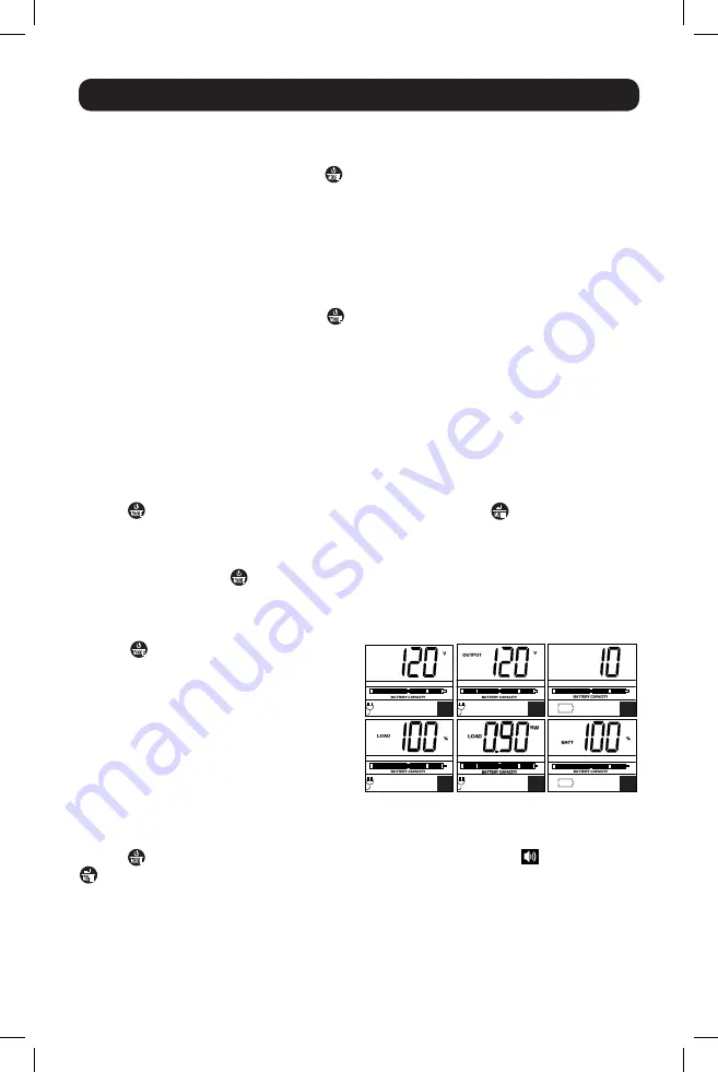
Display Power Conditions 

Use the


MODE


button to advance through  

power conditions. 
1.  Voltage In

2.  Voltage Out

3.  Estimated Runtime (in minutes)

4.  Load %
5.  Load Wattage*

6.  Battery Capacity %

* Load Wattage is displayed in watts up to “999”,  
and then will be displayed in Kilowatts.

Enable/Disable Alarm

Tap the


MODE


button repeatedly to advance to the LCD screen featuring the 

 icon. Press the


MUTE


button to select ON or OFF alarm mode settings. The last option displayed before 

navigating away from this menu option will be the selected setting.

Basic Operation

INPUT

1

2

RUNTIME

MIN

3

4

5

6

17-02-143-9336B5.indb   5

3/14/2017   2:03:53 PM

Summary of Contents for SMART1200LCD

Page 1: ...Features 8 Battery Replacement 9 Storage and Service 11 Product Registration 11 Español 13 Français 25 SMART1500LCD Series Number AG 8869 SMART1500LCDXL Series Number AGSM8191 Not suitable for mobile applications 1111 W 35th Street Chicago IL 60609 USA www tripplite com support Copyright 2017 Tripp Lite All rights reserved PROTECT YOUR INVESTMENT Register your product for quicker service and ultim...

Page 2: ...d under warranty UPS Connection Warnings Connect your UPS directly to a properly grounded AC power outlet Do not plug the UPS into itself this will damage the UPS Do not modify the UPS s plug and do not use an adapter that would eliminate the UPS s ground connection Do not use extension cords to connect the UPS to an AC outlet If the UPS receives power from a motor powered AC generator the generat...

Page 3: ... Battery replacement should be performed only by authorized service personnel using the same number and type of batteries Sealed Lead Acid The batteries are recyclable Refer to your local codes for disposal requirements or visit http www tripplite com support recycling program for recycling information Tripp Lite offers a complete line of UPS System Replacement Battery Cartridges R B C Visit Tripp...

Page 4: ...or the unit s battery will only be accessible after it has been charged for 24 hours STEP 3 Plug your equipment into the UPS Your UPS is designed to support electronic equipment only You will overload the UPS if the total VA ratings for all the equipment you connect to the outlets exceeds the UPS s Output Capacity To find your equipment s VA ratings look on their nameplates If the equipment is lis...

Page 5: ...all tool in the slots on the sides of the display to pop it out of the UPS housing rotate the display and snap it back into the UPS housing LCD Features Tap the MODE button to advance from one display to the next Use the MUTE button to toggle settings for Power Sensitivity Control External Battery Setting Control Scroll Control Alarm LCD Brightness and Self test functions The last option displayed...

Page 6: ...last option displayed before navigating away from this menu option will be the selected setting This setting is normally set to 100 which enables the UPS to protect against waveform distortions in its AC input When such distortion occurs the UPS will normally switch to providing PWM sine wave power from its battery reserves for as long as the distortion is present In some areas with poor utility p...

Page 7: ...XL model only Tap the MODE button repeatedly to advance to the External Battery screen as shown here Press the MUTE button to advance to the next available option The last option displayed before navigating away from this menu option will be the selected setting Note The Battery Runtime calculation is based on this setting This feature setting allows the user to configure the UPS for use with an E...

Page 8: ...REE download at www tripplite com and appropriate USB or DB9 cable Both a USB and a DB9 cable are included with your UPS Notes 1 This connection is optional The UPS will work properly without this connection 2 This UPS System provides basic communication compatibility with most integrated Windows Macintosh and Linux power management applications Battery Backup Protected Surge Protected Outlets Pro...

Page 9: ...tery cartridge For the SMART1500LCDXL model only Tripp Lite BP24V15RT2U external battery pack rated 24Vdc 14Ahr with overcurrent protection should be connected to the external battery pack connector For further information about replacement compatibility and ordering visit Tripp Lite on the Web at http www tripplite com products battery finder To Replace the Batteries 1 Remove the retaining screw ...

Page 10: ... place the new batteries into the UPS and connect the positive red connectors and negative black connectors 5 Reattach the bottom panel and secure using the retaining screw removed in step 1 17 02 143 9336B5 indb 10 3 14 2017 2 04 00 PM ...

Page 11: ...ducts shipped to Tripp Lite or an authorized Tripp Lite service center must have transportation charges prepaid Mark the RMA number on the outside of the package If the product is within its warranty period enclose a copy of your sales receipt Return the product for service using an insured carrier to the address given to you when you request the RMA Visit www tripplite com warranty today to regis...

Page 12: ... Technical Requirements Document s The Department does not guarantee the equipment will operate to the user s satisfaction Before installing this equipment users should ensure that it is permissible to be connected to the facilities of the local telecommunications company The equipment must also be installed using an acceptable method of connection The customer should be aware that the compliance ...

Reviews: