background image

14

Operation 

(continued)

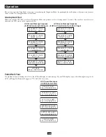
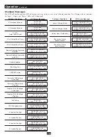
shutdown Messages

Your UPS will shut down and the LCD will display a message if it detects one of the following conditions. Note: During all these conditions, 
the “Input,” “Output” and “Bypass” LEDs will be illuminated.

shutdown Conditions

L1 Extended Overload

L2 Extended Overload

L1 to L2

Output Short Circuit

L1 to N Output Short Circuit

L2 to N Output Short Circuit

Remote Shutdown Command

(via DB9)

Remote Shutdown Command

(via EPO)

Battery Depletion

Site Wiring Fault

EEPROM Failure

Positive DC BUS Voltage

is Too High

Positive DC BUS Voltage

is Too Low

Negative DC BUS Voltage

is Too High

Negative DC BUS Voltage

is Too Low

Fan Failure

UPS Overtemperature

L1 Inverter Too High

L1 Inverter Too Low

SHUTDOWN

L1 O VERLOAD=XXX%

LCD screen Messages

SHUTDOWN

L2 O VERLOAD=XXX%

OP S HORTCIRCUIT

LOAD1 = XX X% X. XKW

OP1  SHORTCIRCUIT

LOAD1 = XX X% X. XKW

OP2  SHORTCIRCUIT

LOAD1 = XX X% X. XKW

REMOTE C OMMAND

LOAD1 = XX X% X. XKW

EMERGENCY STO P!

LOAD1 = XX X% X. XKW

SITE WIR ING F AULT

LOAD1 = XX X% X. XKW

EEPROM FAI L

LOAD1 = XX X% X. XKW

+DC  BUS  HIGH

LOAD1 = XX X% X. XKW

+DC  BUS  LOW

LOAD1 = XX X% X. XKW

-DC  BUS  HIGH

LOAD1 = XX X% X. XKW

-DC  BUS  LOW

LOAD1 = XX X% X. XKW

FAN  FAIL

LOAD1 = XX X% X. XKW

OVERTEMPERATURE

LOAD1 = XX X% X. XKW

LOW  BATTERY

LOAD1 = XX X% X. XKW

INVERTER1 HIG H

LOAD1 = XX X% X. XKW

INVERTER1 LOW

LOAD1 = XX X% X. XKW

L2 Inverter Too High

L2 Inverter Too Low

INVERTER2 HIG H

LOAD1 = XX X% X. XKW

INVERTER2 LOW

LOAD1 = XX X% X. XKW

shutdown Conditions

Internal Charger Failure

External Charger Failure

Battery Open / Bad Battery

Phase Lock Failure,

Bypass Lockout

Phase Lock Failure,

Inverter Lockout

INT  CHARGER F AIL

LOAD1 = XX X% X. XKW

LCD screen Messages

EXT  CHARGER F AIL

LOAD1 = XX X% X. XKW

BAD  BATTERY!

LOAD1 = XX X% X. XKW

BYPASS LOC KOUT

LOAD1 = XX X% X. XKW

INVERTER LOCK OUT

LOAD1 = XX X% X. XKW

Summary of Contents for SmartOnline SU5000RT4U

Page 1: ...SU8000RT4U Not suitable for mobile applications Important Safety Warnings 2 Features 3 Mounting 5 Connection 6 Optional Connection 7 Manual Bypass Operation 8 Operation 10 Internal Battery Replacement...

Page 2: ...erminals may be live even when the UPS is not connected to an AC power source Do not connect surge suppressors or extension cords to the output of your UPS This might overload the UPS and will void th...

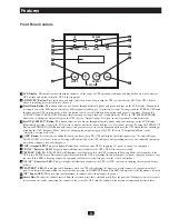
Page 3: ...Configuration Menu in the Operation section for details OFF Button Press this button and hold it until you hear a beep The UPS will display the following message Switch to Bypass N ON Y OFF if it is s...

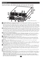
Page 4: ...e the inside of the UPS USB and RS 232 Communication Ports These USB and female RS 232 DB9 serial ports may be used to connect your UPS to a workstation or server They are used with Tripp Lite softwar...

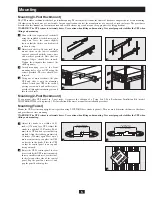
Page 5: ...must determine the fitness of hardware and procedures before mounting If hardware and procedures are not suitable for your application contact the manufacturer of your rack or rack enclosure The proce...

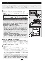
Page 6: ...PS s ON Button A until you hear a beep to begin inverter operation Your UPS will now provide output power through its AC outlets to connected equipment Your UPS will perform a brief self test and show...

Page 7: ...s port 1 2 1a 1b 4 5 2a 2b EPO Pin Assignment 3a 3b External Battery Connection Your UPS comes with a robust internal battery system external batteries are needed only to extend runtime Adding externa...

Page 8: ...disconnect communication cable s from the communication port s A on the UPS power battery module STEP 3 Press the UPS s OFF Button B if the UPS is powered until you hear a beep and see a Switch to By...

Page 9: ...isk of electrical shock Due to the presence of high voltage internal batteries even without AC present these contacts are live Do not let these contacts touch any surface A Contacts on Detachable PDU...

Page 10: ...aC input DIAGNOSTIC MODE INPUT AC OK DIAGNOSTIC MODE INPUT AC BAD DIAGNOSTIC MODE BATTERY OK DIAGNOSTIC MODE BATTERY OK DIAGNOSTIC MODE CHARGER OK DIAGNOSTIC MODE AC DC OK DIAGNOSTIC MODE AC DC OK DI...

Page 11: ...ailable The UPS shuts down if AC power is interrupted The second line of the LCD Display shows basic power conditions Push the SCROLL buttons to browse through these basic power conditions in the sequ...

Page 12: ...w the SET UP screen 1 Press the SCROLL UP SELECT button to enter the UPS SET UP procedure 2 Press the SCROLL UP SELECT button again to enter the OUTPUT SELECT procedure 3 There are 3 output voltage se...

Page 13: ...on on its LCD and stops supplying output power to its load Bypass Voltage Conditions L1 15 Higher Than Nominal Voltage L2 15 Higher Than Nominal Voltage L1 20 Lower Than Nominal Voltage L2 20 Lower Th...

Page 14: ...VERLOAD XXX OP S HORTCIRCUIT LOAD1 XX X X XKW OP1 SHORTCIRCUIT LOAD1 XX X X XKW OP2 SHORTCIRCUIT LOAD1 XX X X XKW REMOTE C OMMAND LOAD1 XX X X XKW EMERGENCY STO P LOAD1 XX X X XKW SITE WIR ING F AULT...

Page 15: ...o ensure that the service problem does not originate from a misreading of the instructions 2 If the problem continues do not contact or return the UPS to the dealer Instead call Tripp Lite at 773 869...

Page 16: ...If the product should prove defective in material or workmanship within that period Seller will repair or replace the product in its sole discretion Service under this Warranty can only be obtained b...

Reviews: