background image

5

Switch

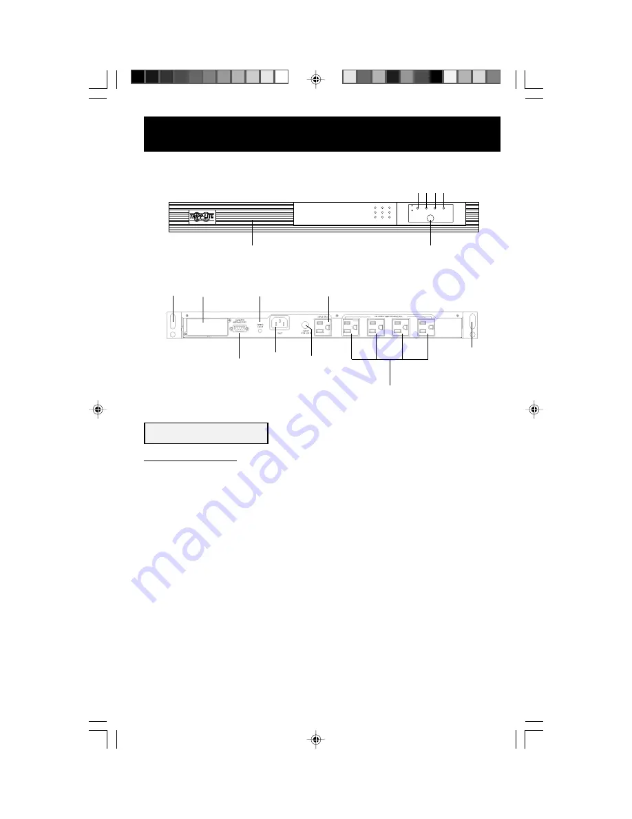
1. Main Power Switch

This switch activates three separate UPS functions:

UPS Power

Press the switch, 

hold it for 3 seconds

 and release it to turn the UPS

ON or OFF.*

Alarm Silence

Press the switch and 

immediately release it

 to silence the UPS Alarm.

UPS Cold Start

Press the switch, 

hold it for 5 seconds

 and release it to turn your UPS

ON and to use it as a stand-alone power source (operating from the
battery without AC input).**

* The UPS will execute a 10-second self-test when you turn it on.  The “Normal" LED will illuminate, and the UPS will beep once
to indicate the UPS is turned ON.  If the UPS alarm sounds and the "Replace Battery" LED illuminates, turn your UPS OFF, let
your UPS charge its batteries for 12 hours and turn UPS back ON to repeat the automatic self-test. If alarm still sounds, contact
Tripp Lite for service. CAUTION: Do not unplug your UPS to test its batteries. This will remove safe electrical grounding and may
introduce a damaging surge into your network connections.

** The "Backup" LED will illuminate since your UPS will operate from battery power.

Basic Operation

2


3


4 5

8

9

6

12

14

10

11

7

11

Front

Back

13

1

200007222 Smart 450 RT Owners Manual [120 Volt].p65

9/7/00, 5:16 PM

5

Summary of Contents for SmartPro 450 RT

Page 1: ...hicago IL 60609 USA CustomerSupport 773 869 1234 www tripplite com Installation p 3 4 Basic Operation p 5 7 Storage Service p 8 Specifications p 8 Safety p 2 Owner s Manual SmartPro 450 RT Intelligent Network UPS System 120V ESPAÑOL p 9 FRANÇAIS p 17 200007222 Smart 450 RT Owners Manual 120 Volt p65 9 7 00 5 16 PM 1 ...

Page 2: ...pecifications Equipment Connection Warnings Do not use Tripp Lite UPS Systems for life support applications in which a malfunction or failure of a Tripp Lite UPS System could cause failure or significantly alter the performance of a life support device Battery Warnings Your UPS does not require routine maintenance Do not open your UPS for any reason There are no user serviceable parts inside Batte...

Page 3: ...ng inside the UPS fill the empty upward facing holes with the plastic plugs included Wallmount To mount the UPS perpendicular to a wall along a straight vertical line first position brackets on the UPS s sides as shown in Figure 3 Adjust brackets to desired distance from wall Use 4 mounting screws and washers to connect the UPS to each bracket Mount UPS to your wall with user supplied screws and h...

Page 4: ...tion program appropriate to your operating system Turn your UPS ON by pressing the Main Power Switch holding it for 3 seconds and releasing it Your UPS is designed to support only computer equipment You will overload your UPS if you connect household appliances laser printers or surge suppressors to the UPS s Battery Supported Outlets DB9 port connection is optional Your UPS will function properly...

Page 5: ...he Normal LED will illuminate and the UPS will beep once to indicate the UPS is turned ON If the UPS alarm sounds and the Replace Battery LED illuminates turn your UPS OFF let your UPS charge its batteries for 12 hours and turn UPS back ON to repeat the automatic self test If alarm still sounds contact Tripp Lite for service CAUTION Do not unplug your UPS to test its batteries This will remove saf...

Page 6: ...ce every second for approximately 2 minutes depending on load prior to shut down 4 Fault Overload LED This red light will illuminate constantly to indicate a short circuit in the UPS or other fault The light will illuminate and the UPS s Alarm will sound constantly for 30 seconds before the UPS automatically shuts down The light will flash and the UPS s Alarm will sound once each second when the U...

Page 7: ...or using the mounting brackets to suit under monitor tower and wallmount applications 12 AC Inlet Receptacle Connect one end of the detachable line cord into this receptacle and the other end into your wall outlet 13 Battery Replacement Door Under normal conditions the original battery in your UPS will last several years Battery replacement should be performed only by qualified service personnel R...

Page 8: ... standards AC Noise Attenuation 40 dB AC TVSS Protection Modes H to N H to G N to G FCC Radio TV Interference Notice Note This equipment has been tested and found to comply with the limits for a Class B digital device pursuant to Part 15 of the FCC Rules These limits are designed to provide reasonable protection against harmful interference in a residential installation This equipment generates us...

Reviews: