background image

3

Quick Installation

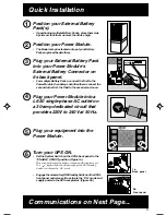
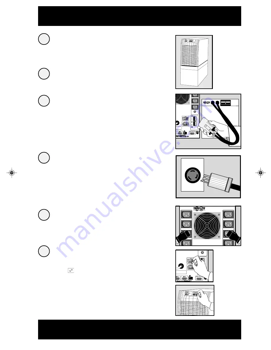
Position your External Battery
Pack(s).

• If positioning multiple Battery Packs, place them side

by side or stack them no more than three high.

Position your Power Module.

• The Module may be stacked on top of your Battery

Packs or placed beside them.

Plug your External Battery Pack
into your Power Module's
External Battery Connector on
its back panel.

• For multiple Battery Packs, connect the first to the

Power Module, then daisy-chain the others: connect the
second to the first, the third to the second, and so on.

Plug your Power Module into a
L6-30 single-phase AC outlet on
a 30-amp dedicated circuit that
provides 220V to 240V at 50 Hz.

Plug your equipment into the
Power Module.

Turn your UPS ON.

• Set the System Switch on the UPS's back panel to the

“ENABLE” (RIGHT) position. (Figure 1a)

This switch activates the battery charger and microprocessor.
The “

” light will flash until you engage the ON/Standby

Switch to activate the “ON” mode.

• Engage the momentary ON/Standby Switch on the UPS's

front panel and release it to activate the “ON” mode and
supply power to the UPS receptacles. (Figure 2b)

2

1

3

Communications on Next Page...

4

5

6

00VA 4500W
M 50/60HZ 5000VA 3700W

50HZ 5000VA 3700W

CAUTION: DO NOT UNPLUG WHILE

OPERATING OR ARCING WILL OCCUR

36VDC 175 AMPS MAX

BRANCH CIRCUIT #1

230VAC 10AMPS

50/60HZ 5000VA 4500W

30VAC NOM 50/60HZ 5000VA 3700W
0VAC NOM 50HZ 5000VA 3700W

CAUTION: DO NOT UNPLUG WHILE

OPERATING OR ARCING WILL OCCUR

36VDC 175 AMPS MAX

BRANCH CIRCUIT #1

230VAC 10AMPS

1a.
Back panel

2b.

Front panel

9905251 230V SmartPro Datacenter OM.p65

8/8/00, 2:02 PM

3

Summary of Contents for SmartPro Datacenter INT

Page 1: ...f Tripp Lite Quick Installation p 3 4 Basic Operation p 5 7 Storage Service p 8 Specifications p 8 Safety p 2 1111W 35thStreet Chicago IL 60609 USA CustomerSupport 773 869 1234 www tripplite com Owner sManual SmartPro Datacenter INT Intelligent Line Interactive UPS Systems 230V Output ...

Page 2: ...lure or significantly alter the performance of a life support device Do not connect surge suppressors to the output of your UPS This may damage your UPS and will void both the surge suppressor and UPS warranties Battery Warnings Your UPS does not require routine maintenance Do not open your UPS for any reason There are no user serviceable parts inside Battery replacement must be performed by quali...

Page 3: ...ur equipment into the Power Module Turn your UPS ON Set the System Switch on the UPS s back panel to the ENABLE RIGHT position Figure1a This switch activates the battery charger and microprocessor The light will flash until you engage the ON Standby Switch to activate the ON mode EngagethemomentaryON StandbySwitchontheUPS s front panel and release it to activate the ON mode and supply power to the...

Page 4: ...which port Note the last switch on the right has no function 3 2 1 Computer communications are optional Your UPS will function properly without these connections The LAN 4 1 or Smart DB9 port is always enabled and is not controlled by the LAN Interface DIP Switches If you do not connect a computer to any of the LAN 2 1 DB9 ports set their corresponding LAN Interface DIP Switches to the DEACTIVATE ...

Page 5: ...ous beep that cannot be silenced will alert you to immediately shut down connected equipment Test your UPS s battery charge Leave your connected equipment ON With your UPS plugged in and completely turned ON engage this switch hold it there for 5 seconds and release it You will hear a series of short beeps as the UPS momentarily switches to battery to test its charge The light will turn ON and the...

Page 6: ...ged If it lights let the UPS charge for 12 hours then perform a self test If the light continues to stay on contact Tripp Lite for service This multi colored light displays 4 separate UPS load conditions It will turn from green low to yellow medium to red high as you connect equipment to show you the load level your UPS is supporting When the light is red your UPS is supporting a load above 85 of ...

Page 7: ...ipment during power failures This port uses RS 232 communications to transmit UPS and power conditions Pin 7 Transmit Pin 8 Common Pin 9 Receive Contact Tripp Lite Customer Support for more information and a list of available SNMP network management and connectivity products Contact Closure Ports Lower Rear Panel These ports labeled LAN 2 2 on the Control Module are also used to connect your UPS t...

Page 8: ...s within the 2 year warranty period enclose a copy of your sales receipt Specifications SMARTDC3000INT SMARTDC3000XRINT Output Capacity VA Watts 3000 2400 3000 2400 Battery Runtime with Battery Pack with 1 BP36V33 with 1 BP36VXR for Half Load Full Load in Minutes 26 11 84 36 Battery Recharge Time 2 4 hrs 2 4 hrs Approvals SMARTDC5000INT SMARTDC5000XLINT Output Capacity VA Watts 5000 3750 5000 3750...

Reviews: