background image

8

Basic Operation 

continued

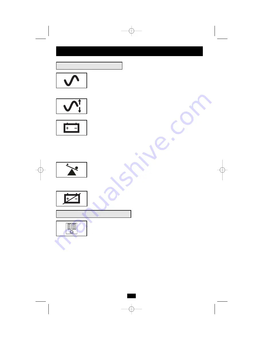
Indicator Lights (Front Panel)

POWER:

Lights green when the UPS is receiving AC power.

Illuminates constantly when the UPS is in the 

ON

mode, indicating

that batteries are charging and connected equipment is receiving filtered
AC power. Flashes while in 

STANDBY

mode to indicate that batteries

are charging but connected equipment is not receiving power.

VOLTAGE CORRECTION:

Lights green whenever your UPS is

automatically correcting high or low AC line voltage. The UPS will
also click. These are normal, automatic UPS operations, and no
action is required on your part.

BATTERY CHARGE:

This multicolored light displays 7 separate

UPS battery charge conditions. It will turn from red (low) to yellow
(medium) to green (full) to show you the level of battery charge. If
the light is constant, your UPS is in the 

ON

or 

STANDBY

mode,

operating from line power, and the battery is charging. If the light is
flashing, your UPS is in the 

INVERT

mode, operating from battery,

and the battery is discharging. If the light is flashing red, your UPS is
in 

INVERT

and is nearly out of power: you should save files and shut

down your equipment immediately.

OUTPUT LOAD:

This multicolored light shows how heavy your

UPS’s load is. Steady green indicates a light load, steady yellow a
medium load. When the light is red, your UPS is supporting a load
above 85% of its capacity. If the red light begins flashing, then your
UPS is severely overloaded. Immediately remove load from the UPS
until the light stops flashing.

BATTERY WARNING:

Lights red if your UPS’s self-test (initiated

with the Mute/Test Switch) reveals a low battery charge or internal
fault. If this light turns on, let the UPS charge for 12 hours then perform
a second self-test. If the light stays on, contact Tripp Lite for service.

AC Receptacles:

Your UPS has 15-amp outlets that provide 120V AC

power. These output receptacles supply your connected equipment
with AC line power during normal operation and battery power during
blackouts and brownouts. The UPS protects equipment connected to
these receptacles against damaging surges and line noise. If you have
a DB9 or USB connection to your UPS, you can remotely reboot con-
nected equipment by turning the UPS 

OFF

and 

ON

using Tripp Lite’s

PowerAlert Software. See software instructions for details.

Other UPS Features (Rear Panel)

15 amp NEMA 5-15R

200208099 93-2040 SM1000RMX Owner’s Manual.qxd  9/12/2002  3:53 PM  Page 8

Summary of Contents for SmartPro RMX RMX 1000-2000 VA

Page 1: ...unting 3 Connection 5 Basic Operation 7 Storage and Service 10 Copyright 2002 Tripp Lite All rights reserved SmartPro is a registered trademark of Tripp Lite SmartPro RMX 1000 2000 VA 120V Input Output UPS Systems Intelligent Line Interactive Industrial Cabinet Specifications 10 200208099 93 2040 SM1000RMX Owner s Manual qxd 9 12 2002 3 53 PM Page 1 ...

Page 2: ...connect extension cords or surge suppressors to the output of your UPS This may damage your UPS and will void both the surge suppressor and UPS warranties Battery Warnings Your UPS does not require routine maintenance Do not open your UPS for any reason except battery replacement There are no user serviceable parts inside Battery replacement must be performed by qualified service personnel Because...

Page 3: ...user supplied rack bolts D through its mounting ears and into the rack s side supports 2 Suggested Rackmount Installation for the SM1000RMX Mounting Suggested 4 Post Rackmount Installation for the SM2000RMX 1 Connect the three segments of each shelf A using the included screws nuts and washers B Leave the screws slightly loose so that the shelves can be adjusted in the next step Adjust each shelf ...

Page 4: ...ls 3 1 Attach the four mounting shelf segments shown A to both rack posts B with the screws nuts and washers provided C Note that the side supports should face inward Attach mounting ears D to the middle mounting holes of your UPS E using the screws and washers provided F Do not attach the mounting ears to your equipment s front holes Using an assistant if necessary lift your UPS and slide it onto...

Page 5: ...your equipment into your UPS Your UPS is designed to support only computer equipment You will overload your UPS if you connect household appliances laser printers or surge suppressors to the UPS s outlets Turn your UPS ON Press the POWER button Hold the button for a moment until the LED stops flashing and illuminates constantly Release the button Your UPS is now ON and its AC outlets are active Co...

Page 6: ...ripp Lite power protection software appropriate to its operating system If your UPS has two USB ports a second computer with a USB port may be connected if desired EPO Port Connection Select Models Only Using the RJ11 cable provided connect the Emergency Power Off EPO port of your UPS to a user supplied normally closed or normally open switch according to the circuit diagram below The EPO port is ...

Page 7: ...Your UPS has three alarms The first the INVERT alarm emits four short beeps every ten seconds when the UPS is in INVERT mode to warn you that AC power has failed The second the OVERLOAD alarm emits short rapid beeps when the UPS is in INVERT mode if the total power draw of connected equipment exceeds the UPS s output capacity to warn you to reduce the load The third the Low Battery alarm emits a c...

Page 8: ... and shut down your equipment immediately OUTPUT LOAD This multicolored light shows how heavy your UPS s load is Steady green indicates a light load steady yellow a medium load When the light is red your UPS is supporting a load above 85 of its capacity If the red light begins flashing then your UPS is severely overloaded Immediately remove load from the UPS until the light stops flashing BATTERY ...

Page 9: ...ent during a blackout see Connection page 5 EPO Emergency Power Off Port Select models only Your UPS may have an EPO port that can be used to connect the UPS to a con tact closure switch to enable emergency inverter shutdown see Connection page 5 Accessory Slot Select models only Remove the small cover panel from this slot to use optional accessories to remotely monitor and control your UPS Contac...

Page 10: ... 147 volts Voltage Regulated Output Voltage Range 120 9 On Battery Output Voltage Range 120 5 Output Waveform Line Mode filtered sinewave Output Waveform Battery Mode PWM sine wave AC Surge Suppression exceeds IEEE 587 Cat A B standards AC Noise Attenuation 40 dB AC Surge Protection Modes H to N H to G N to G This device complies with part 15 of the FCC Rules Operation is subject to the following ...

Page 11: ...11 200208099 93 2040 SM1000RMX Owner s Manual qxd 9 12 2002 3 53 PM Page 11 ...

Page 12: ...93 2040 200208099 200208099 93 2040 SM1000RMX Owner s Manual qxd 9 12 2002 3 53 PM Page 12 ...

Reviews: