background image

7

7. Equipment Installation

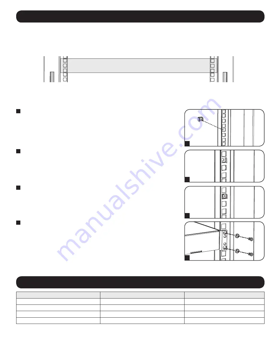
7.1 Installing or Removing Cage Nuts

Warning: Do not install equipment until you have stabilized the enclosure. Install heavier equipment first and install it towards the bottom 

of the enclosure. Install equipment starting from the bottom of the enclosure and proceeding toward the top of the enclosure - never the 

reverse. If using sliding equipment rails, be careful when extending the rails. Do not extend more than one set of sliding equipment rails 

at one time. Avoid extending sliding equipment rails near the top of the enclosure.

Note: The square holes in the middle of each rack unit are numbered and also include a small notch to aid identification. A single rack unit includes the space 
occupied by the numbered hole and the holes directly above and below.

To Remove Cage Nuts, Reverse Steps 1-3

Note: You may wish to use a cage nut tool (user-supplied) to aid cage nut installation and removal.

WARNING: The flanges of the cage nuts should engage the sides of the square opening in the rail, not the top and bottom. Follow the 

instructions in your equipment documentation to ensure proper installation of your equipment.

1

    Locate the numbered square openings in the mounting rails where you plan to install your 

equipment. You will install cage nuts (included) into the square openings in order to provide an 

attachment point for the mounting screws (included). 

Note: Consult your equipment 

documentation to determine how many cage nuts will be required and where they will need to 

be installed.

2

    From the inside of the mounting rail, insert one of the flanges of the cage nut through the 

square opening. Press it against the side of the square opening. Each flange should engage one 

side of the square opening, not the top or bottom.

3

   Compress the cage nut at the sides slightly to allow the remaining flange to fit through the 

square opening. When the cage nut is properly installed, both flanges will protrude through the 

square opening and will be visible on the outer surface of the mounting rail. Repeat steps 1-3 
until all required cage nuts are installed.

4

    After installing the required cage nuts, use the included mounting screws and cup washers to 

secure your equipment to the rack rail. Place the cup washers between the screws and the 

equipment mounting brackets.

Note:  Your equipment may also include mounting hardware. Read the mounting instructions that came 
with your equipment before installing your equipment.

8. Specifications

Model

SRW12UHD 

SRW18UHD

Dimensions (H x W x D)

24.46 x 36.1 x 24.77” (621 x 917 x 629 mm)

35.96 x 36.1 x 24.77” (913 x 917 x 629 mm)

Unit Weight

101.4 lb (46 kg)

119.9 lb (54.4 kg)

Load Capacity

500 lb (226.8 kg)

500 lb (226.8 kg)

Mounting Depth (Adjustable)

19.36 – 30.36” (491.74  – 771.14 mm)

19.36 – 30.36” (491.74  – 771.14 mm)

20

19

18

22

21

20

19

18

22

21

20

19

18

22

21

20

19

18

22

21

24

25

26

27

28

29

23

22

21

20

19

18

24

25

26

27

28

29

23

22

21

20

19

18

24

24

2

1 Rack Unit

1

2

3

4

Summary of Contents for SmartRack SRW12UHD

Page 1: ...nting Rails 5 5 4 Adjusting Mounting Rail Depth 5 6 Wall Mounting the Enclosure 6 7 Equipment Installation 7 7 1 Installing or Removing Cage Nuts 7 8 Specifications 7 9 Storage and Service 8 10 Warranty Warranty Registration 8 Español 9 Français 17 Owner s Manual Wall Mounted SmartRack Enclosure Models SRW12UHD SRW18UHD 1111 W 35th Street Chicago IL 60609 USA www tripplite com support Copyright 20...

Page 2: ...l installation location as possible Install the enclosure in a structurally sound area capable of handling the load or on a level floor that is able to bear the weight of the enclosure all equipment that will be installed in the enclosure and any other enclosures and or equipment that will be installed nearby Use caution when cutting packing materials The enclosure could be scratched causing damag...

Page 3: ...3 3 Feature Identification 1 Locking Removable Side Doors 2 Locking Removable Front Panel 3 Vertical Mounting Rails 4 Removable Cable Access Hole Covers 5 Vents 1 2 3 1 4 5 ...

Page 4: ...en removed If you plan to store the enclosure for an extended period before installation follow the instructions in the Storage and Service section All parts of the enclosure are grounded to the frame of the enclosure Connect one of the two quick disconnect grounding wires to the hole provided on the inside of either of the side doors and connect the other quick disconnect grounding wire to any of...

Page 5: ...nted to the wall before mounting any equipment inside Also be sure to have all the right adjustments on your rails before mounting equipment See below for Adjusting Mounting Rail Depth Warning Do not attempt to adjust rails while equipment is installed in the enclosure Do not attempt to use rails without screws installed 2 per rail The 4 mounting rails are pre installed to accommodate equipment wi...

Page 6: ...losure into mounting position with the doors installed Always remove doors prior to lifting to reduce the enclosure s weight Using a level measure to position your mounting areas precisely Use appropriate fasteners not included to secure the enclosure to the wall Warning The area you plan to mount the enclosure to must be able to withstand the weight of the enclosure and all mounted equipment For ...

Page 7: ...e mounting screws included Note Consult your equipment documentation to determine how many cage nuts will be required and where they will need to be installed 2 From the inside of the mounting rail insert one of the flanges of the cage nut through the square opening Press it against the side of the square opening Each flange should engage one side of the square opening not the top or bottom 3 Comp...

Page 8: ... nameplate label along with all required approval markings and information When requesting compliance information for this product always refer to the series number The series number should not be confused with the marketing name or model number of the product Tripp Lite has a policy of continuous improvement Specifications are subject to change without notice 9 Storage and Service 10 Warranty and...

Page 9: ...3 5 4 Ajuste de la profundidad del riel 13 de montaje 6 Instalando el gabinete en la pared 14 7 Instalación de equipos 15 7 1 Instalación o extracción de las tuercas de jaula 15 8 Especificaciones 15 9 Almacenamiento y servicio 16 10 Garantía 16 English 1 Français 17 Manual del propietario Gabinete SmartRack para instalar en la pared Modelos SRW12UHD y SRW18UHD 1111 W 35th Street Chicago IL 60609 ...

Page 10: ...ca posible del lugar de instalación Instale el rack en una zona estructuralmente sana capaz de soportar la carga con piso nivelado que pueda soportar su peso el de todos los equipos que se instalarán en él y cualquier otro rack o equipos que se instalarán cerca Corte el material de embalaje con precaución El rack podría rayarse causando daños que no están cubiertos por la garantía Guarde los mater...

Page 11: ...as características 1 Puertas laterales removibles y con cerradura 2 Panel frontal removible y con cerradura 3 Rieles para Instalación Vertical 4 Cubierta removible para el agujero de acceso de los cables 5 Ventilas 1 2 3 1 4 5 ...

Page 12: ...narlo durante un período prolongado antes de instalarlo siga las instrucciones de la sección Almacenamiento y servicio Todas las partes del gabinete se conectan a tierra con el marco del gabinete Conecte uno de los dos cables de conexión a tierra de rápida desconexión al agujero provisto dentro de cualquiera de las dos puertas laterales y conectar el otro cable de conexión a tierra de rápida desco...

Page 13: ...nstalado firmemente en la pared antes de instalar cualquier equipo dentro de él Asegúrese también de realizar todos los ajustes adecuados de rieles antes de montar los equipos Consulte la sección siguiente para ver el Ajuste de la profundidad del riel de montaje Advertencia No intente ajustar los rieles mientras los equipos están instalados en el rack No intente utilizar rieles sin tornillos insta...

Page 14: ...l gabinete a su posición de instalación con las puertas instaladas Quite siempre las puertas antes de levantar el gabinete para reducir el peso del gabinete Use un nivel para determinar con precisión la posición de las áreas de instalación Use sujetadores adecuados no incluidos para asegurar el gabinete a la pared Advertencia El área donde se planea instalar el gabinete debe poder soportar el peso...

Page 15: ...uidos Nota Consulte la documentación del equipo para determinar la cantidad de tuercas de jaula que serán necesarias y dónde deberán instalarse 2 Desde adentro del riel de montaje inserte una de las bridas de la tuerca en jaula a través de la abertura cuadrada Presiónela contra el lado de la abertura cuadrada Cada brida debe engancharse en un lado de la abertura cuadrada ni arriba ni abajo 3 Compr...

Page 16: ...e el número de serie El número de serie no debe ser confundido con el nombre de identificación ni con el número de modelo del producto Tripp Lite tiene la política de mejora continua Las especificaciones están sujetas a cambios sin notificación previa 9 Almacenamiento y servicio 10 Garantía Almacenamiento El rack debe almacenarse en un ambiente interior controlado lejos de la humedad las temperatu...

Page 17: ...e montage 21 5 4 Ajuster la profondeur des rails 21 de montage 6 Montage mural du boîtier 22 7 Installation de l équipement 23 7 1 Installer ou retirer les écrous à cage 23 8 Spécifications techniques 24 9 Entreposage et entretien 24 10 Garantie 24 English 1 Español 9 Manuel de l utilisateur Boîtier mural SmartRack Modèles SRW12UHD et SRW18UHD 1111 W 35th Street Chicago IL 60609 USA www tripplite ...

Page 18: ...é déplacé le plus près possible de l endroit définitif où l armoire sera installée Installez l armoire dans un endroit capable de supporter la charge ou sur un plancher au niveau capable de supporter le poids del armoire de tout équipement qui sera installé dans l armoire ou tout autre armoire et ou équipement qui sera installé à proximité Prenez toute les précautions nécessaires en découpant les ...

Page 19: ...cation des pièces de l armoire 1 Portes latérales verrouillables amovibles 2 Panneau avant verrouillable amovible 3 Rails de montage verticaux 4 Couvercles amovibles des trous d accès aux câbles 5 Évents 1 2 3 1 4 5 ...

Page 20: ...de protection Si vous prévoyez d emtreposerl armoire pour une durée prolongée avant de l installer suivez les instructions de la section Entreposage et entretien Toutes les parties du boîtier sont mises à la masse sur le cadre du boîtier Brancher un de deux fils de mise à la masse à déconnexion rapide au trou qui se trouve à l intérieur d une des portes latérales et brancher l autre fil de mise à ...

Page 21: ...23 Avertissement S assurer que le boîtier est monté au mur de façon sécuritaire avant de monter l équipement à l intérieur Vérifiez également l ajustement des rails avant d y monter l équipement Voir ci dessous pour l ajustement de la profondeur des rails de montage Attention N essayez pas d ajuster les rails de montage avec de l équipement installé dans l armoire N utilisez pas les rails sans les...

Page 22: ...llustré dans le diagramme Remarque Ne pas soulever le boîtier en position de montage avec les portes installées Toujours enlever les portes avant de soulever afin de réduire le poids du boîtier Utiliser un niveau mesurer avec précision la position des zones de montage Utiliser des fixations appropriées non incluses pour retenir le boîtier au mur Avertissement L emplacement où vous prévoyez monter ...

Page 23: ...t de fixation aux vis de montage fournies Remarque Consultez la documentation de votre équipement pour déterminer combien d écrous à cage seront nécessaires et où ils devront être installés 2 Insérer une des brides des écrous à cage dans l ouverture carrée depuis l intérieur du rail de montage Enfoncez la sur le côté de l ouverture carrée Chaque bride doit entrer dans le côté de l ouverture carrée...

Page 24: ... le numéro de série Il ne doit pas être confondu avec le nom de la marque ou le numéro de modèle du produit La politique de Tripp Lite est celle d une amélioration continuelle Les spécifications techniques peuvent être modifiées sans préavis 9 Entreposage et entretien 10 Garantie Entreposage L armoire doit être entreposée dans un environnement intérieur contrôlé à l abri de l humidité des températ...

Reviews: